

Audio AMP. will this fry my I/o lines?
 Dgswaner
Posts: 795
Dgswaner
Posts: 795
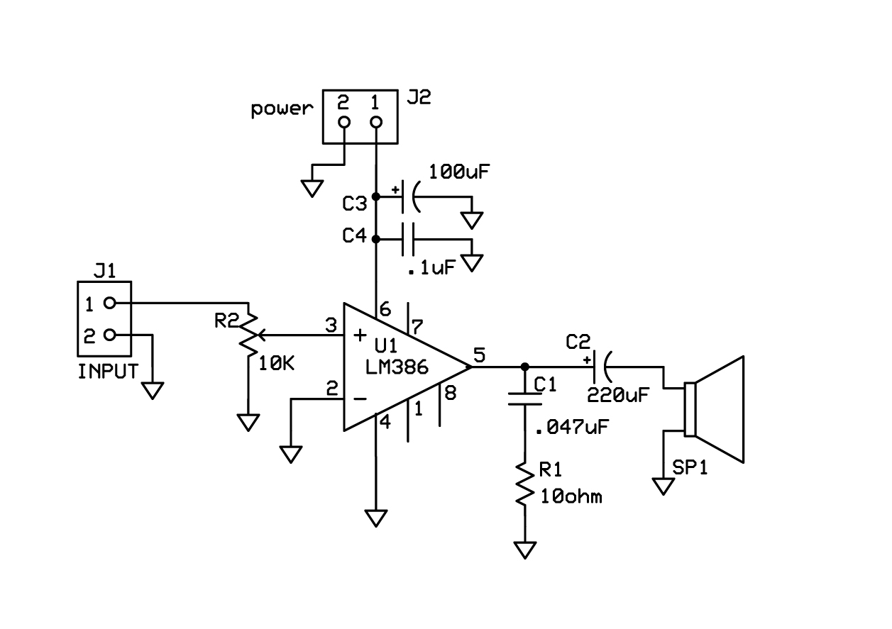
I was planning on using this circuit to power a speaker for audio feed back and eventually a text to speech module. I used a variation of this circuit for a guitar amp effect. and it worked great. I didn't consider it being a problem but I read a post (can't find it now) about someone who did something similar and it fried their emic module. can I get some input on this being Stamp/propeller friendly or not? should I add diodes or resistors to the i/o lines?
your input would be appreciated.
data sheet
www.nteinc.com/specs/800to899/pdf/nte823.pdf
the NTE823 is a drop in replacement for the LM386 and is what I'll actually be using.
▔▔▔▔▔▔▔▔▔▔▔▔▔▔▔▔▔▔▔▔▔▔▔▔
A complex design is the sign of an inferior designer. - Jamie Hyneman, Myth Buster
your input would be appreciated.
data sheet
www.nteinc.com/specs/800to899/pdf/nte823.pdf
the NTE823 is a drop in replacement for the LM386 and is what I'll actually be using.
▔▔▔▔▔▔▔▔▔▔▔▔▔▔▔▔▔▔▔▔▔▔▔▔
A complex design is the sign of an inferior designer. - Jamie Hyneman, Myth Buster
1257 x 887 - 93K
Comments
Not quite sure if you were going to connect a stamp to the output to monitor output....Emic output to this circuit??
The stamps can source 20mA and I think sink 35mA. There are clamping diodes in the stamp (not sure about the propellor) that will handle excess voltages fine (20Volts me thinks) but a series resistor is generally used to keep the current down to prevent killing the I/O pin.
▔▔▔▔▔▔▔▔▔▔▔▔▔▔▔▔▔▔▔▔▔▔▔▔
<FONT>Steve
What's the best thing to do in a lightning storm? "take a one iron out the bag and hold it straight up above your head, even God cant hit a one iron!"
Lee Travino after the second time being hit by lightning!
▔▔▔▔▔▔▔▔▔▔▔▔▔▔▔▔▔▔▔▔▔▔▔▔
A complex design is the sign of an inferior designer. - Jamie Hyneman, Myth Buster
With the EMIC, you have to use the AOUT output pin and that needs a series capacitor to block the DC bias on that pin. A 10uF capacitor should work fine.
▔▔▔▔▔▔▔▔▔▔▔▔▔▔▔▔▔▔▔▔▔▔▔▔
A complex design is the sign of an inferior designer. - Jamie Hyneman, Myth Buster