SSR Box -- Solid-State Relay "How To"
The SSR Box
Solid-State Relay Circuit and Implementation
Members have asked about using solid-state relays [noparse][[/noparse]SSRs], their usages, and controlling AC via a Stamp, many times.· I decided to make a project and a tutorial, too.· This way the information will be easy to find (if somebody will actually use http://search.parallax.com)· If it doesn't make it as a "sticky thread" it'll be there by typing in "SSR", "solid-state", or "solid-state relay."· When in future somebody starts a subject along these lines then I'll point them right here.
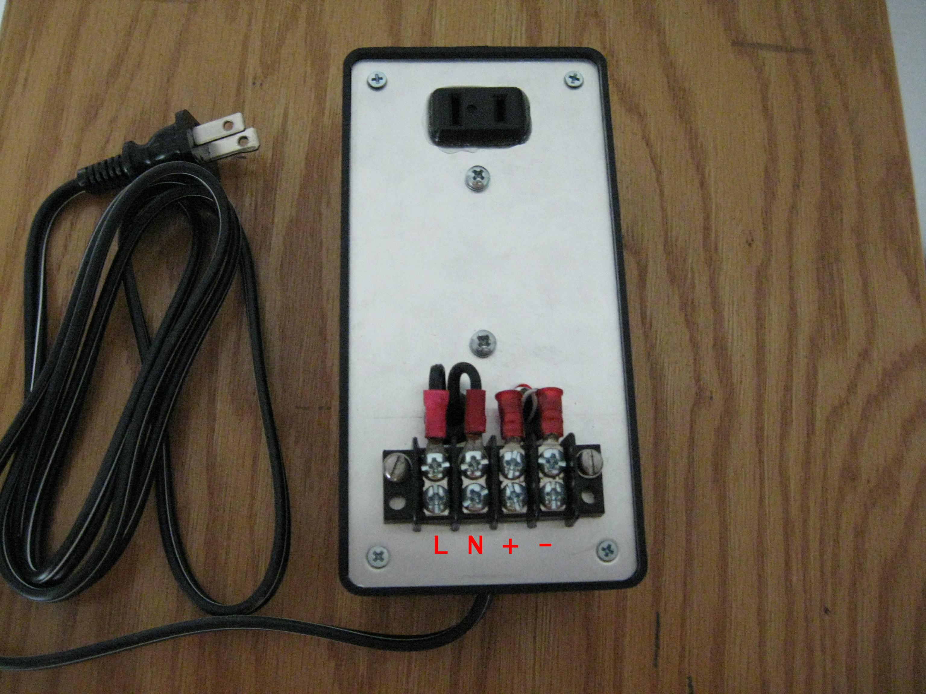
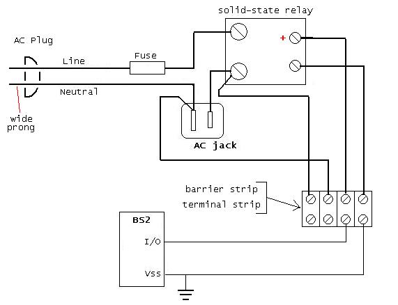
The SSR-Box is composed of an SSR, an input fuse (very important), a terminal strip and a panel-mount AC jack, all mounted in a RadioShack project box.
I think the schematic says it all for the circuitry.· The SSR switched output is available at the AC panel jack and on the terminals of the barrier strip.· I think the AC panel jack is really handy, especially for controlling appliances.· Stop hacking cords already.· The panel jack is a "snap-in" sort of thing that I also epoxied the bajabbers out of (it's
going nowhere.)· Anyway, yours could have only one or the other, or both.
The Control inputs are wired out to the barrier strip, too.· The wires pass through grommetted holes ("inside.jpg" shows them best.)· I'm stuck on positive logic, where we equate on/1/high, so I connect the SSR "+" DC control terminal to a Stamp Output pin and the "-" control terminal to Ground/Vss.· As the SSR's DC input is (internally) an LED in series with a resistor, no additional limiting is needed.
The Demo program is simply a routine that cycles an output pin, no big deal, that's all it takes.
Finally, here's a youtube link to a demo with a HomeWork Board
controlling a string of lights SSR-Box and then switching a lamp:
http://www.youtube.com/watch?v=i57eJ8I_elU


Comments
My one recommendation is to use two different terminal strips.
I'm sure you'll get some nice shrapnell if someone were to connect their stamp to the wrong terminal strip points.
Also, if you use a separate strip, you could get one of those plexiglass covers to protect against shock!
(just a thought!)
▔▔▔▔▔▔▔▔▔▔▔▔▔▔▔▔▔▔▔▔▔▔▔▔
<FONT>Steve
What's the best thing to do in a lightning storm? "take a one iron out the bag and hold it straight up above your head, even God cant hit a one iron!"
Lee Travino after the second time being hit by lightning!
I like your presentation. No complaints.
Should a ground line be shown in the schematic? I never wire up without a three terminal plug.
I didn't use a 3-pronged cord on the input.· I'll have to give that some thought.
Several posts were removed from this thread. Nobody was singled out but it really got too long and off topic and was really getting out of hand. I see two sides here and I respect both. PJ, you’re trying to provide and example of how to connect an SSR. That is great and you have made some effort to ensure safety. Not everyone believes the barrier strip is sufficient. Let’s focus on the fact that whenever working with AC or any high voltage/current system you should always consider safety first. That said anyone who uses this project concept should think about fusing, isolation, etc. One example may not fit every application. Let’s move forward·on this. Remember everyone, have fun and safety first! Take care.
▔▔▔▔▔▔▔▔▔▔▔▔▔▔▔▔▔▔▔▔▔▔▔▔
Chris Savage
Parallax Tech Support
Post Edited (Chris Savage (Parallax)) : 11/5/2007 3:54:07 PM GMT
http://www.mouser.com/ProductDetail/Clare/CPC1966B/?qs=sGAEpiMZZMsUriz2CNI3E1D7Zk0ZityoX28w%252brq7AvU%3d
-Tommy