

How much noise is expected?
 clemen2
Posts: 10
clemen2
Posts: 10
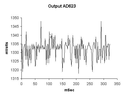
··········· There have been many discussions about adc methods and woes, but I still have a question.· I am using a load cell (output 0-30 mV) to measure force. ·I am using a AD623 ·Instrumentation Amplifier to amp the 0-30 mV signal (amp set to factor of ~ 211 by external resister).· This signal is then sent for digital conversion to a MAX1202 chip.· Using the documentation available for these IC’s I have been able to set up a functioning circuit that is read by the prop.· As far as I can tell the 1202 is working great thanks to a .spin post by James Long.· My problem is the noise in the amped signal out of the AD623- at 1300 mV (subtracting an offset) I am getting about +/- 11 mV (stdev = 5.4).· This is about a 0.8% error in the amp. ·At zero volts the error is similar, stdev = 4.8. ·I have included a graph of output to visualize the noise.
·
··········· For a power I’m using a converted computer power source.· The IC chips are working of +5/-5 volts.· The circuit is set up on a breadboard. ·Naturally there are computer monitors and a computer (within inches) of the breadboard and a wireless router and fluorescent lights within feet.
·
··········· These errors seem high to me but before I spend too many more days tinkering with power supplies and low pass filters I wanted to get impressions from folks about the size of these errors.
·
Thanks
Cliff Lemen
·
··········· For a power I’m using a converted computer power source.· The IC chips are working of +5/-5 volts.· The circuit is set up on a breadboard. ·Naturally there are computer monitors and a computer (within inches) of the breadboard and a wireless router and fluorescent lights within feet.
·
··········· These errors seem high to me but before I spend too many more days tinkering with power supplies and low pass filters I wanted to get impressions from folks about the size of these errors.
·
Thanks
Cliff Lemen
474 x 368 - 24K
Comments
WHAT YOU NEED:
1. Linear regulator and decoupling caps for the AD623.
2. PCB with proper ground planes (even on 2-layer)
PC PSUs are fine for digital logic but they aren't designed for sensitive analog circuits. Also, the PSU won't regulate effectively unless it has quite a bit of load on it's +5V line as this is the line it monitors.
You can breadboard digital circuits to some degree but breadboarded analog circuits are only good for functional checks. Amplifiers do what they do best, amplify. If you have PSU noise and ground noise and radiated noise, well, they are just going to amplify it.
*Peter*
Your noise is around 50 uV which is something one should have to live with in many cases. According to your diagram its spectrum seems to be mostly in the kHz area, so it could be easily suppressed by a simple first oder low-pass (10kOhm + 100nF). This can easily be incorporated into your amplifier, if you use an opamp.
I would note that the noise I am getting looks very similar if battery power is used instead of the PC power supply, so in this case, I don't see the power supply as the big problem.
As for low pass filters what I used was a filter on the input side of the amp- I have included a fig from Analog Devices.· They always say get C1-C3 as close as possible- closer than a breadboard can???· I toyed around with another low pass filter between the amp and the adc chip- so far it has not helped, but I will follow this up.
As far as using a mean or median of a set of readings, that's always an option and as expected it reduces the error but at the cost of speed.· Right now that is how I have it programmed, but I still hope to get a better signal to start with.
You need:
digital and analog ground separated
ground planes
a good OpAmp (don't know how good yours is)
filtering of the supply-voltages *very* near to the OpAmp
Filtering of the input and output (with low-ESR-caps)
think about where you connect the signal ground
low noise metal film Rs
You do *not* want a breadboard with long connections that work like antennas.
Nick
▔▔▔▔▔▔▔▔▔▔▔▔▔▔▔▔▔▔▔▔▔▔▔▔
Never use force, just go for a bigger hammer!
The DIY Digital-Readout for mills, lathes etc.:
YADRO
Nick M covered most issues.
I would also add " Use shielded cable from Load cell to circuit"
cheers
Ron Melbourne OZ
And you can also add "make an shielding around the OpAmp (HF-case)".
Nick
▔▔▔▔▔▔▔▔▔▔▔▔▔▔▔▔▔▔▔▔▔▔▔▔
Never use force, just go for a bigger hammer!
The DIY Digital-Readout for mills, lathes etc.:
YADRO
What is this Yadro ??
Ron Melbourne Oz
· I have been looking into making·three layer·PCB with split planes analog and digital power and grounds, maybe a better power source, maybe better components, the load cell cable is already shielded.· I have been working on the artwork for the three layers and I have to admit the ground and power planes really make the design simple.· And I reading up on the do's and don't's of EMI control.· So I am making headway, but how much improvement will I likely see from this?
· Of course that can't be answered directly because you don't know how well I can design and build this multilayer PCB- but has anyone done this with the prop chip and a adc circuit with high amping (200x) and gotten better than +/-·15-20 mV?· If you just look at the spec sheets for the amp and adc I should be to do much better.· But this is the real world.
·
Leon
▔▔▔▔▔▔▔▔▔▔▔▔▔▔▔▔▔▔▔▔▔▔▔▔
Amateur radio callsign: G1HSM
Suzuki SV1000S motorcycle
It is a link. If you click it, you'll find a description.
Back to the OpAmp.
You also might have a look at reference-designs for ADCs above 12 bits. They'll show you clever layouts and point you what to pay attention for.
And for the OpAmp, I would look first what LT has to offer. They also do have good appnotes and layout-suggestions.
And last but not least, I guess a single rail opamp won't do it in this case.
HTH,
Nick
▔▔▔▔▔▔▔▔▔▔▔▔▔▔▔▔▔▔▔▔▔▔▔▔
Never use force, just go for a bigger hammer!
The DIY Digital-Readout for mills, lathes etc.:
YADRO