

Solar car - help needed
 computer guy
Posts: 1,113
computer guy
Posts: 1,113
My school has entered me and seven others into the local solar car challenge.
The rules are:
You must use a 30W panel.
You can use batteries, however they must not exceed 2 VAHr.
The cars in the race are usually about 60cm long 30cm wide and 10cm tall.
How would you connect batteries to work with the solar panel?
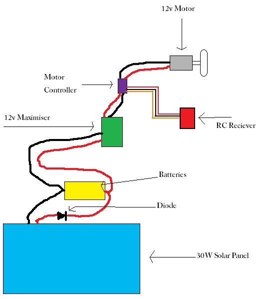
What extra electronics would you use to get the most power out of the car? We are already using a 12v mini maximiser.
This is our current setup.

Thank you
▔▔▔▔▔▔▔▔▔▔▔▔▔▔▔▔▔▔▔▔▔▔▔▔
Check out my robot using the propeller RECONAUTOR
Post Edited (computer guy) : 10/25/2007 8:29:29 AM GMT
The rules are:
You must use a 30W panel.
You can use batteries, however they must not exceed 2 VAHr.
The cars in the race are usually about 60cm long 30cm wide and 10cm tall.
How would you connect batteries to work with the solar panel?
What extra electronics would you use to get the most power out of the car? We are already using a 12v mini maximiser.
This is our current setup.
Thank you
▔▔▔▔▔▔▔▔▔▔▔▔▔▔▔▔▔▔▔▔▔▔▔▔
Check out my robot using the propeller RECONAUTOR
Post Edited (computer guy) : 10/25/2007 8:29:29 AM GMT
517 x 598 - 26K
Comments
Voltage control rather than power control may provide less to the motor. The 30 watt solar panel makes no mention of voltage output. What happens if voltage output is less than the charged battery due to overcast skies? Does it still provide a useful power suppliment or does the battery merely discharge until below the solar cells output voltage takes over?
If the motor controller can tolerate higher peaks, I suspect the motors can too. So that is the first item I would try to do without. The 12volt battery really charges at a higher voltage, roughly 14 volts.· Do you really expect the battery to go into a charge mode during operation?
You can build your own discrete MOSfet component motor controller [noparse][[/noparse]H-bridge or other] to handle a wide range of thresholds. The R/C receiver must be tolerated as is. Verify it isn't much of your power budget. If it is PWM, why are you bothering with PWM output? If it needs +5 regulated, but can use +7.2 regulated - decide which voltage uses the least power [noparse][[/noparse]including the regulator].
You can use a low dropout regulator to the reciever that will widen the voltage range and in some cases provide a regulated voltage even when the battery is below the target voltage. You just have to read a lot of regulator PDFs to find the best. Try www.futurelec.com for an easy place to research many manufacturers.· Maybe the R/C reciever has a built-in regulator already.· Maybe you need to consider a different R/C setup to optimize power and simplify control.
You MUST have a blocking diode at the solar panel to avoid the panel discharging the battery during dark periods, but some diodes drop the voltage by 0.7volts and other [noparse][[/noparse]geranium Shotky diodes I believe] cause less of a drop.· But this circuit assumes the battery will be charged by the solar panel at times.
Motors with planetary gears and real ball bearings will run more efficently. Having heavy and balanced wheels, while initially hard to start [noparse][[/noparse]use the battery to get going] will act as flywheels and sustain forward motion through power slumps.
Consider switching back and forth between battery and solar according to actual RPM and available power from battery and solar.·[noparse][[/noparse]Use an SX28·with internal clock and 3.3v power to get a 2ma·microprocessor.]·This would require a feedback of the true wheel motion.
I suspect in an actual competative run, the battery may·never be in a solar charge mode [noparse][[/noparse]you need all the solar power to go to the wheels], so don't bother with that.· Just optimize any and all available solar power to the motor and have the battery take over when levels won't provide forward motion.
While the lables on the batteries may all say 12V 2AH, some will charge to a much higher intial voltage due to product variation.· Test lots of batteries to find out while really is giving you the most voltage with the 2AH.
Weight is an obvious factor.· Putting weight in the wheels enhances inertia, but other on-board weight can slow you down.· Lithium batteries are more engergy dense that lead acid, so will reduce over all drag.·And motors with newer stronger magnets [noparse][[/noparse]neodium] may be lighter, but more powerful.
At the end of the day, there is a lot you can do if you have deep pockets and design specifically to the contest rules and exploiting what they don't say.· Being generic will not win the prize.
▔▔▔▔▔▔▔▔▔▔▔▔▔▔▔▔▔▔▔▔▔▔▔▔
PLEASE CONSIDER the following:
Do you want a quickly operational black box solution or the knowledge included therein?······
Post Edited (Kramer) : 10/25/2007 10:03:01 AM GMT
The motor controller is a small 4cm by 2cm device from a hobby shop. It does the job.
The receiver is powered from 4 x AA batteries (the rules do allow this).
Is there any way of storing extra power in capacitors to last up to 1 min to allow for short dark periods.
Thank you
▔▔▔▔▔▔▔▔▔▔▔▔▔▔▔▔▔▔▔▔▔▔▔▔
Check out my robot using the propeller RECONAUTOR
I assume there's a track to compete on?
Is it flat, what kind of surface?
Will other cars be on the track at the same time?
What kind of events?
One thing you may want to include is small motors to tilt the solar panel to maximize the output.
(You'll want it to be within +/- 10degrees)
▔▔▔▔▔▔▔▔▔▔▔▔▔▔▔▔▔▔▔▔▔▔▔▔
Don't visit my new website...
The track is a flat concrete car park. with a plastic border for the actual track.
The idea is to do as many laps as you can in one hour.
Our design has the wheels and so forth mounted directly to the case of the panel. therefore tilting is not an option.
Thank you
▔▔▔▔▔▔▔▔▔▔▔▔▔▔▔▔▔▔▔▔▔▔▔▔
Check out my robot using the propeller RECONAUTOR
You'll definitely want to maximize your efficiency....
▔▔▔▔▔▔▔▔▔▔▔▔▔▔▔▔▔▔▔▔▔▔▔▔
<FONT>Steve
What's the best thing to do in a lightning storm? "take a one iron out the bag and hold it straight up above your head, even God cant hit a one iron!"
Lee Travino after the second time being hit by lightning!
Can you think of anything else that may help.
Thank you
▔▔▔▔▔▔▔▔▔▔▔▔▔▔▔▔▔▔▔▔▔▔▔▔
Check out my robot using the propeller RECONAUTOR
·
Do you have a choice in the type of Solar cell?
·
Amorphous Silicon will be more sensitive to lower levels of light than Polycrystalline Silicon.· Amorphous Silicon will also require about 40% more area to produce the same amount of·Wattage as Polycrystalline Silicon.· ·
·
·
Amorphous Silicon - 13% efficient
Amount of surface area required for 30Watts = 6 square feet
·
Polycrystalline Silicon - 18% efficient
Amount of surface area required for 30Watts = 4.3 square feet
·
Monocrystalline Silicon - 24% efficient
Amount of surface area required for 30Watts =·3.25 square feet
Basically as a rule, the larger the surface area, the more sensitive to lower levels of light the solar panel will be.
·
▔▔▔▔▔▔▔▔▔▔▔▔▔▔▔▔▔▔▔▔▔▔▔▔
Beau Schwabe
IC Layout Engineer
Parallax, Inc.
Marty
▔▔▔▔▔▔▔▔▔▔▔▔▔▔▔▔▔▔▔▔▔▔▔▔
Lunch cures all problems! have you had lunch?
Lawson that mini-maximiser in the pic is the one we are using.
Why wouldn't it work with the batteries included in the circuit?
Where can I buy a peak power tracker, and how much are they?
wouldn't removing the diode be a bad idea as it would discharge the batteries during dark periods?
We are given a solar panel to work with. the panels look liked ripped bits of blue shiny paper smooshed between a pane of glass.
Thank you
▔▔▔▔▔▔▔▔▔▔▔▔▔▔▔▔▔▔▔▔▔▔▔▔
Check out my robot using the propeller RECONAUTOR
2. The 'Power-maximizer' may be withholding power until a certain threshold of voltage is reached.· That is often how Beam Engines work.·
3. Not sure that the blocking diode is useful in a competative setting.· The trade off is a bit more power without one·if it is a very sunny day compared to potentially a bit less power if it is a very·cloudy day.· Maybe you just have to configure it immediately before the competition by looking at the weather.· Every little bit counts.· But if you have large capacitors, you may need the blocking diode for other reasons.
4. In model car racing, often lower voltage motors·have been·used on higher voltages in order to gain more speed and acceleration.· [noparse][[/noparse]Yes, this may eventually shorten the useful life of the motor - but it need only survive one hour.]
Do you have to use a 12 volt motor?· Maybe a 9V or 6V will do better?· I really doubt that you are going to burn up the motor in a one hour competition.· This is all about the coil windings being different size.·The lower voltage rating will consume·current more quickly, but give you more speed.·If there is·marginal voltage, it·may use all of it while a higher voltage motor may not. In general, they use the same insulation and brushes, so the 'breakdown voltages' are probably well over 50 volts.· Of course, the motors·may run hotter.·But, you may get more laps in an hour AND you·may have more momentum to carry you through dark periods if you find a way to allow the motor to avoid slowing you down during dark periods [noparse][[/noparse]It might be best to have a mechanical freewheeling mode when the motors are not turning.· The worst thing is to allow the motor to create a back EMF]· But also, you are going to have to better control steering at a faster speed.
5. Does your steering require the motors be powered to steer?· Driving two wheels differentially requires constantly available·power to the motors.· It seems to me that when you loose power, you temporarily loose the ability to steer.· Consider one very efficient motor to drive forward motion and an R/C servo· or small geared motor with H-bridge to steer.· Are two wheel motors really better than one in this situation?
6. Adding capacitors to collect the sun?· Most supercaps are rated at about 5.5volts.· So you would have to stack three of them in series to provide for 12VDC, ovtherwise they will blow up.· You could have parallel stacks.· The question is what do they do at startup?· They need to either take an initial charge from the solar panel and/or the battery.· There may be some problems with in-rush current being excessive if charged from the battery.· If not charged from the battery, you may need to keep them on the same side of the blocking diode as the solar panal.· If they let you charge your capacitors with sunlight·prior to the start of the race, you've gotten some extra energy.
I suspect you'll have to make a list of all the possible improvements and run tests to get the best combo.
▔▔▔▔▔▔▔▔▔▔▔▔▔▔▔▔▔▔▔▔▔▔▔▔
PLEASE CONSIDER the following:
Do you want a quickly operational black box solution or the knowledge included therein?······
Here's the 'original document'.
http://www.voltscommissar.net/minimax/minimax.htm
▔▔▔▔▔▔▔▔▔▔▔▔▔▔▔▔▔▔▔▔▔▔▔▔
PLEASE CONSIDER the following:
Do you want a quickly operational black box solution or the knowledge included therein?······
The supercap idea sounds good. So 3 supercaps in series going from solar panel to caps to diode to rest of car, should provide more of a boost of power in cloudy day situations.
Thank you
▔▔▔▔▔▔▔▔▔▔▔▔▔▔▔▔▔▔▔▔▔▔▔▔
Check out my robot using the propeller RECONAUTOR
What value diode would you use to reduce loss of power?
Thank you
▔▔▔▔▔▔▔▔▔▔▔▔▔▔▔▔▔▔▔▔▔▔▔▔
Check out my robot using the propeller RECONAUTOR
Use a SCHOTTKY diode with Low voltage drop... here are a couple that would probably work for you.
http://pdf1.alldatasheet.com/datasheet-pdf/view/24608/STMICROELECTRONICS/STPS20L15G.html - 20A <= 0.33V drop
http://pdf1.alldatasheet.co.kr/datasheet-pdf/view/29721/TOSHIBA/10FWJ2C48M.html - 10A <= 0.47V drop
Note: 30Watts @12V will only be 2.5Amps ... So in looking for diodes you want to find a rating that is at least twice that (<-- Good rule of thumb)
....Another important thing to consider in your design to make it more energy efficient, is to make it as light weight as possible
▔▔▔▔▔▔▔▔▔▔▔▔▔▔▔▔▔▔▔▔▔▔▔▔
Beau Schwabe
IC Layout Engineer
Parallax, Inc.
Post Edited (Beau Schwabe (Parallax)) : 10/27/2007 5:42:15 AM GMT
Thank you
Last years car had a random diode used with it as the people from our school had no idea about electronics.
This years car will have the right diode. Probably the STPS20L15G.
Last years car was light and although this years solar panel is slightly heavier to begin with we hope to get it to as light as or lighter than last years car.
The maximiser is working great for startup time on last years car, although as soon as the sun goes behind even a small cloud the car drops to about 1.2 m/h (just a guess).
Just in case the maximiser causes problems on the day I plan on adding a switch to bypass it.
Edit: I will have to post footage of the race on my website when I can.
The race is on 30th November, in Albury NSW Australia.
Thank you
▔▔▔▔▔▔▔▔▔▔▔▔▔▔▔▔▔▔▔▔▔▔▔▔
Check out my robot using the propeller RECONAUTOR
Polarity is quite important, these are electrolitics. In series of three, it should be +-+-+- so that you avoid trouble. And the + goes to the solar panel's + output while the - goes to solar panel's - output [noparse][[/noparse]in parallel]
One problem I haven't discusses is your 'diode logic'. If you are very concerned, there should be TWO blocking diodes - one to keep the solar panel from draining the super caps and another to keep the battery from charging the super caps.
This is the problem with multiple power sources that can work also as power drains. Are the blocking diodes really going to help significantly or just rob power?
I also see the 'mini-maximizer' has a big diode on board that might be exchanged for a Schottky diode to gain some efficency - just maybe. [noparse][[/noparse]This is the freewheeling diode, you need the SF52.]
The idea here is to learn how to enhance the design rather than 'junk it up'. The Germans had the most accurate artillery during WWII, but the guns had 20-30 moving parts. In warfare, the Americans did better with lesser guns as they had only 7 moving parts. Americans simply had less down time.
And.· I think you should run some test with heavy wheels to add momentum.· There are huge potential losses involved in the mechanical side of this design - maybe 25-30%.
▔▔▔▔▔▔▔▔▔▔▔▔▔▔▔▔▔▔▔▔▔▔▔▔
PLEASE CONSIDER the following:
Do you want a quickly operational black box solution or the knowledge included therein?······
Post Edited (Kramer) : 10/27/2007 12:27:50 PM GMT
1 Farad 5.5V Super Capacitors do the job. How much time would we get before they completely discharged?
Thank you
▔▔▔▔▔▔▔▔▔▔▔▔▔▔▔▔▔▔▔▔▔▔▔▔
Check out my robot using the propeller RECONAUTOR
The rate of discharge depends on the load, the sun's recharge, and maybe the batteries - very complex. With the 'mini-maximizer' and the R/C receiver involved, you cannot simply calculate it.
But, using RC time curves, you might get an ideal absolute maximum and then derated it by 50% as a rough blind guess to try to make observations against.
The formulas are:
C * dV/ct = I or C * dV/ct = -V/R and C is simply equal to 1 farad.
The units are farads, ohms, and seconds.
So t = RC and for example at 25 ohms load t = 25*1 = 50 seconds. But derate it by 50%, you have 12.5 seconds.
If the 'mini-maximizer' and the batteries narrow the useful range of dV, wouldn't that mean even less time?
And, as I mentioned before - you cannot rob Peter to pay Paul.
If the competition doesn't allow you to charge the supercaps with solar power before the start, you are going to have to luckily have a surplus of useful solar energy during the race before you get any real benefit. In other words they may only provide a better advantage on a brighter day.
This reminds me a lot of Formula One racing. All the cars are nearly alike, so little things that can be changed due to weather and track may win the day. In Formula One, they mostly change tires and set suspension. The drive trains are almost identical.
I think a configuration with multiple options and having a lot of practise runs with using a photographic light meter to observe what works, will give you a good idea of how to configure on race day.
▔▔▔▔▔▔▔▔▔▔▔▔▔▔▔▔▔▔▔▔▔▔▔▔
PLEASE CONSIDER the following:
Do you want a quickly operational black box solution or the knowledge included therein?······
Will pass the ideas onto the group, we will experiment using the ideas discussed and see what works.
Thank you
▔▔▔▔▔▔▔▔▔▔▔▔▔▔▔▔▔▔▔▔▔▔▔▔
Check out my robot using the propeller RECONAUTOR
How did you calculate the voltage drop.
The diodes that you suggested aren't available locally.
I am thinking of a 100v 6A diode - p600a.
Data sheet
Thank You
▔▔▔▔▔▔▔▔▔▔▔▔▔▔▔▔▔▔▔▔▔▔▔▔
Check out my robot using the propeller RECONAUTOR
"How did you calculate the voltage drop?" - I looked at the forward voltage drop on the datasheet.
The diode you mention, the p600a, has a maximum Forward voltage of 1.0V ... That's going the wrong direction.
▔▔▔▔▔▔▔▔▔▔▔▔▔▔▔▔▔▔▔▔▔▔▔▔
Beau Schwabe
IC Layout Engineer
Parallax, Inc.
It has a rating of 3A.
Data sheet
Thank you
▔▔▔▔▔▔▔▔▔▔▔▔▔▔▔▔▔▔▔▔▔▔▔▔
Check out my robot using the propeller RECONAUTOR
Also a note on the caps. 1Farad caps are typically BIG - yes they can store a voltage but the room needed may not be there.
The blocking diodes are there to prevent back flows in the power. Solar panels consume power when dark or below the existing voltage charge in a battery and / or capacitor.
With the diode, the circuit 'pumps' electricity into the system and it stays there. Usually diodes have a voltage drop of 0.7 volts while Schottky diodes can get down to 0.3 volt [noparse][[/noparse]yes, the info is in the data sheets, but you should get a few -maybe from different manufacturers - and test for the best one as production varies]. As I recall, the Schottky diodes you Geranium rather than Silicon as a material. Geranium diodes were quite popular in early batteryless radios.
▔▔▔▔▔▔▔▔▔▔▔▔▔▔▔▔▔▔▔▔▔▔▔▔
PLEASE CONSIDER the following:
Do you want a quickly operational black box solution or the knowledge included therein?······
That would be fine.... What it really boils down to is how much you are willing to sacrifice in terms of power loss when it could be delivered in a useful way somewhere else.
The lower the Vf , obviously the more power you have for what immediately counts. I don't know what kind of detrimental effects there would be if you supplied more power to the solar cells then they were able to provide (thus the function of the diode) ... I have never heard of anyone "smoking" their solar cells that way, but I don't know for sure. You may shorten the life and efficiency of the solar cell by removing the diode (<-If a cloud moves in the way) ... but again I'm not sure.
What I do know, is that if your Vf is 0.525V and you are pulling 2.5 Amps, then your diode will need to dissipate 1.3125 Watts of heat. (P = I * V) Consequently, that is how much you are loosing from your 30 Watt panel, so instead of 30 Watts, you now only have 28.7 Watts.
Suppose you have a Vf of only 0.33V, then at 2.5 Amps you would only need to dissipate 825 milliWatts. That allows you to deliver 29.2 Watts to the remainder of your circuitry.
I know it doesn't sound like much, but what if your are in a situation where you tied someone in the race? That extra 1/2 Watt could be the tie breaker.
Trivial? Nah, I just feel that you should understand what role each component plays into the design. The diode is however not something to dwell on, you need to either make an executive or group decision and stick with it.
There are most likely going to be other obstacles before you reach your design goal that are going to make the diode decision seem even more trivial. Don't despair, There are several people here in the forums that are more than willing to help out with ideas. All you need to do is ask.
▔▔▔▔▔▔▔▔▔▔▔▔▔▔▔▔▔▔▔▔▔▔▔▔
Beau Schwabe
IC Layout Engineer
Parallax, Inc.
This is exactly what i was trying to convey regarding the use of a diode. I mean if the car is to win and win at all cost then i would investigate all the possible looses of energy. This diode in my opinion is a sure obvious sign of loss of energy.
I would also think about wheels; making them as thin as possible to minimize friction.
As far as I understand the diode is a good idea, yes some power loss however it will protect the caps/batteries from discharging the wrong direction.
Thank you
▔▔▔▔▔▔▔▔▔▔▔▔▔▔▔▔▔▔▔▔▔▔▔▔
Check out my robot using the propeller RECONAUTOR
I will have to explore solar panels more because of the great questions being delivered thought out this form.
Ordering a solar panel today.
·
"Is it not a diode itself?" - yes, but with every diode there is a reverse breakdown voltage (Google "Zener Effect"... What the Zener voltage is for a solar Cell I don't know,·I'm sure that it varies.
If however the Solar Cells Zener voltage is reached, then your batteries or power supply would be shorted across the Solar Cell(s).
·
Edit
·
·
... Of course The Zener effect is accumulative per cell,· and you’re going to have a Zener effect with an external diode as well.· The only thing that I can figure then, and I get a hint of it from reading, is that the leakage resistance of the Solar cell itself is pretty high.(<--Read low resistance)... so while the sun is not shining on the cells, there is adequate resistance to "discharge" your battery source.· By adding an external diode, you eliminate this internal leakage resistance assuming that the leakage resistance of the external diode is relatively low. (<--Read High resistance).· Other than providing this type of isolation, the external diode is probably not necessary.
·
The most cause for concern are hot spots caused from shading.· Here is where an external diode can be very beneficial, but it only applies to several panels that are in series.
·
http://www.udel.edu/igert/pvcdrom/MODULE/Bypass.htm
http://www.udel.edu/igert/pvcdrom/MODULE/HotSpot.htm
▔▔▔▔▔▔▔▔▔▔▔▔▔▔▔▔▔▔▔▔▔▔▔▔
Beau Schwabe
IC Layout Engineer
Parallax, Inc.
Post Edited (Beau Schwabe (Parallax)) : 10/30/2007 4:28:59 PM GMT