Shop OBEX P1 Docs P2 Docs Learn Events
BASIC stamp 2 and Infra-red — Parallax Forums

BASIC stamp 2 and Infra-red

FrozeyFrozey Posts: 8
edited 2007-10-20 19:19 in BASIC Stamp
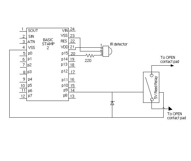
I am currently working on a project that opens a lock using the universal IR remote kit from parallax. I am using a modified version of Amal Graafstra's RFID keyless lock from the book "RFID Toys" The IR remote kit has the IR detector, and a 220 ohm resistor. I also have a 5VDC/1A SPST Reed Relay with a a low power switching diode(radio shack part number 276-1122) soldered on the top of the relay , and I am using the wieser powerlock 1000 electronic deadbolt as my lock. I was wondering if you guys could take a look at my schematic and let me know if the circuit would work properly...and also if there is anything that needs to be added, or possible somethings that are not neccesary in my circuit and can be removed

Thank you all in advance

Post Edited (Frozey) : 10/20/2007 2:30:17 AM GMT
614 x 520 - 25K

Comments

  • Mike GreenMike Green Posts: 23,101
    edited 2007-10-20 02:32
    I think you've got your IR detector pin numbers backwards. Check the datasheet on Parallax's website.
  • FrozeyFrozey Posts: 8
    edited 2007-10-20 02:39
    I'm pretty sure it's correct....i took a look at the diagram for it : http://www.parallax.com/dl/docs/prod/compshop/IRremoteAppKit.pdf

    and it looks right to me...who know, there is a very good chance i am wrong...I am still very very new to basic stamp 2 and the like.

    Thanks for your help Mike....other then the pins does everything else look alright?
  • Mike GreenMike Green Posts: 23,101
    edited 2007-10-20 03:00
    Yeah. There's very little circuitry in what you've got. You did remember to put the diode across the coil ... great!

    I compared the two diagrams and the numbering is different in the two, but the connections are the same.
  • D FaustD Faust Posts: 608
    edited 2007-10-20 13:26
    A stamp can't drive a 1A relay from a pin, you need a transistor!

    ▔▔▔▔▔▔▔▔▔▔▔▔▔▔▔▔▔▔▔▔▔▔▔▔
    --DFaust
  • FrozeyFrozey Posts: 8
    edited 2007-10-20 13:32
    Thank you for your help guys!

    DFaust...could you elaborate a little on what kind of transistor i need...and where it needs to go? I thought that each I/O pin on the BS2 can source 20 mA and sink25 mA...i could be way off again here...

    Thank you! [noparse]:)[/noparse]

    Post Edited (Frozey) : 10/20/2007 1:46:05 PM GMT
  • D FaustD Faust Posts: 608
    edited 2007-10-20 13:37
    You need to connect the base of a transistor (doesn't matter to much as, long as it can handle 5V, 1A; Logic level would probably be best. You would connect one side of the relay coil to ground and the other to 5V through the transistor. When the transistor is put on by the stamp the relay will be triggered. Then stamp can only supply 25mA I think.

    ▔▔▔▔▔▔▔▔▔▔▔▔▔▔▔▔▔▔▔▔▔▔▔▔
    --DFaust
  • FrozeyFrozey Posts: 8
    edited 2007-10-20 13:46
    Thank you very much once again for all of your help...i really appreciate it and im learning a lot which is always good. I'll keep you guys posted about my progress.


    Thanks
  • Beau SchwabeBeau Schwabe Posts: 6,568
    edited 2007-10-20 14:34
    You need to make sure that the Hfe (Gain) of your transistor is at least 50.· Since the I/O can only source 20mA and you want to drive 1000mA, then the transistor Gain needs to be at least 1000mA/20mA or have a value of 50, and that's pushing it.· If you can find a transistor with a higher Hfe then that would be even better (less current that the Stamp needs to deliver).

    Take a look at the article below, it shows using a Motor, but a relay would be applicable here as well.
    http://forums.parallax.com/attachment.php?attachmentid=37701


    ▔▔▔▔▔▔▔▔▔▔▔▔▔▔▔▔▔▔▔▔▔▔▔▔
    Beau Schwabe

    IC Layout Engineer
    Parallax, Inc.

    Post Edited (Beau Schwabe (Parallax)) : 10/20/2007 2:39:55 PM GMT
  • Mike GreenMike Green Posts: 23,101
    edited 2007-10-20 15:01
    Frozy,
    I think others got confused about your notation for a 5V/1A reed relay. I understood it as a 5V coil reed relay with contacts rated at 1A. Often you can get these with a coil that draws maybe 20ma and that will work fine off a Stamp I/O pin without a driver transistor. If you have a relay whose coil draws more than 20-25ma, then you will need a driver transistor.
  • FrozeyFrozey Posts: 8
    edited 2007-10-20 17:11
    Mike,

    I am fairly sure that the relay will work fine on its own. If anyone has any questions about the relay, it can be found at:

    http://www.radioshack.com/product/index.jsp?productId=2062478&cp=&parentPage=search
  • Mike GreenMike Green Posts: 23,101
    edited 2007-10-20 17:20
    Yeah, I've got a couple of these around somewhere ... they work fine on a Stamp pin (as long as you have the diode).
  • FrozeyFrozey Posts: 8
    edited 2007-10-20 17:29
    Perfect Mike,

    I think that i am good to go. the only thing i need to purchase is the Wieser lock...other than that I am ready for putting it together, and after that...the coding. I am not sure how to proceed with this, but i suppose i could browse around for similar projects and use their code as a base for mine.

    Thank you everyone for your help,
    Frozy
  • Mike GreenMike Green Posts: 23,101
    edited 2007-10-20 17:54
    You don't have to have the lock to begin learning and coding and testing ... Just use a buzzer or LED or some other indicator switched by the relay contacts. Work through the examples in the IR Remote for the BoeBot tutorial. Once you have the Stamp reading the remote control's codes, you're most of the way there.
  • FrozeyFrozey Posts: 8
    edited 2007-10-20 17:56
    Thanks for the tip Mike, that a very good point!
  • D FaustD Faust Posts: 608
    edited 2007-10-20 19:19
    Sorry for starting all of the confusion.· I didn't want anything burning up, and I always see around here that you are supposed to use a transistor.

    ▔▔▔▔▔▔▔▔▔▔▔▔▔▔▔▔▔▔▔▔▔▔▔▔
    --DFaust
Sign In or Register to comment.