I don't suppose you'd like to explain this a little bit in English... or Spanish... or Russian...anything but Swedish. My automated interpreter just doesn't get Swedish.
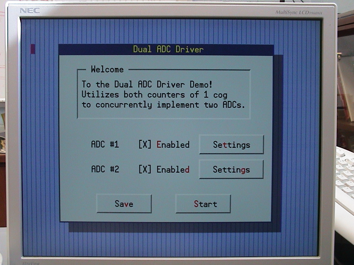
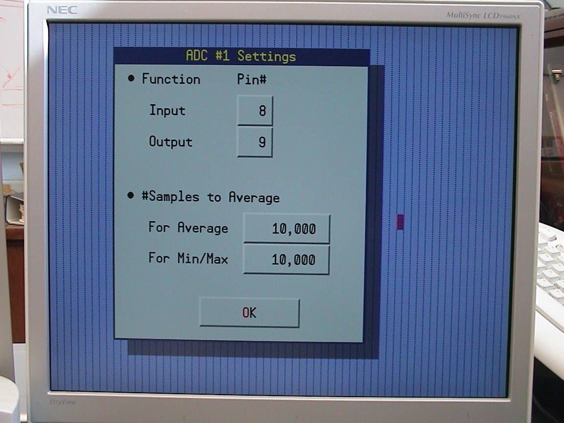
If you have the "demo" board, you can use the default settings·and ADC#1 to look at the onboard microphone signal.· The demo board already has the resistors and capacitors to use Pin#8 as input and Pin#9 as output for ADC (see circuit here http://www.parallax.com/dl/docs/prod/prop/PropDemoDschem.pdf).
The display continuously updates while running and displays the current sample.· In practice, you probably want to smooth this out by averaging.· That's what the "Average" is for.· You can adjust how many samples are averaged to form the next average value.· Does the same thing for the Min and Max value of the samples...
See the "Microphone2VGA" demo object for additional info on the demo board setup...
Here's a photo of a little test setup I have on the "Demo" board for testing ADC#2.· I'm using Pin#6 for input and Pin#7 for output.· Both resistors are 100K, both caps are 1nF.· This is basically the same as the microphone circuit, but for DC rather than AC input.· The pot is 1K, connected between Vdd and Vss, and makes the voltage that I'm measuring.
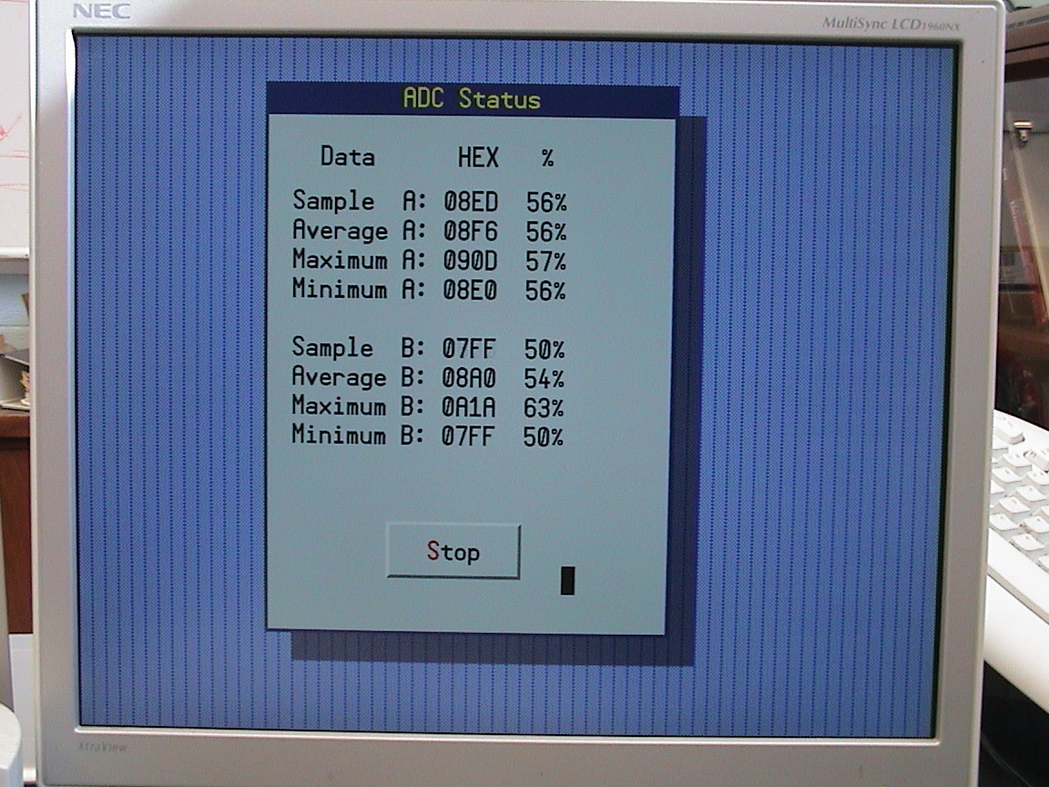
Test Results:
Well, it works pretty good, except for a·small dead zone, right around 50% (between 48 and 52%).· Not too bad though.· The range is not exactly as full as you might think.· I read 100% with only 2.9 V applied and 13% with 0 V applied.
This dead zone must be due to some Schmitt Trigger or hysteresis at·Vdd/2 (?)
No there is no Schmitt Trigger with the Prop inputs.
The voltage at the Prop Input and the cap is ALWAYS around 1.65V.
When you set your pot to the same voltage, there is not much headroom for a current to flow through the 100k input resistor.
I think this is one of the cases, where you should lower the Rs (and thus increase the C)! But no, that will not make any difference....
And BTW: Nice work!
Post Edited (deSilva) : 10/17/2007 10:50:42 PM GMT
Just did some testing with 10k on the prop side, 15k input side, 1k pot for input across 3.3V and 1nF caps...
Still getting a glitch at 50% even with smaller resistances.· It may have something to do with my excessively long leads...· I do have some surface mount components and a board I can bake them on...· May have to up my game here!
Anyway, here's how bad it looks:· (Actually, it doesn't look too bad above 50%.· If I can't fix things, I may try to map my input range to be between 50 and 100%)
Ok, before going SMT, I tried things out with short leads on the Proto board and:· It works beautifully now!· Got a nice, linear response over the full range...· Here's a photo of the setup and a graph of the results:·
Here's a more meaningful test (for me anyway), measuring higher voltages.· I used my new web applet (shameless plug here: http://www.pulsedpower.net/Applets/Electronics/SigmaDeltaADC/SigmaDelta.html) to look at what would be good resistors to measure the +/- 50 V range and came up with R1=10K and R2=330K.· Using these and the same 1nF caps, here are the results (see attached image).· As you can see, the measurement is quite linear, but there is an offset from the expected result.


Comments
Ray,
I don't suppose you'd like to explain this a little bit in English... or Spanish... or Russian...anything but Swedish. My automated interpreter just doesn't get Swedish.
Rich
If you have the "demo" board, you can use the default settings·and ADC#1 to look at the onboard microphone signal.· The demo board already has the resistors and capacitors to use Pin#8 as input and Pin#9 as output for ADC (see circuit here http://www.parallax.com/dl/docs/prod/prop/PropDemoDschem.pdf).
The display continuously updates while running and displays the current sample.· In practice, you probably want to smooth this out by averaging.· That's what the "Average" is for.· You can adjust how many samples are averaged to form the next average value.· Does the same thing for the Min and Max value of the samples...
See the "Microphone2VGA" demo object for additional info on the demo board setup...
·
Test Results:
Well, it works pretty good, except for a·small dead zone, right around 50% (between 48 and 52%).· Not too bad though.· The range is not exactly as full as you might think.· I read 100% with only 2.9 V applied and 13% with 0 V applied.
This dead zone must be due to some Schmitt Trigger or hysteresis at·Vdd/2 (?)
The voltage at the Prop Input and the cap is ALWAYS around 1.65V.
When you set your pot to the same voltage, there is not much headroom for a current to flow through the 100k input resistor.
I think this is one of the cases, where you should lower the Rs (and thus increase the C)! But no, that will not make any difference....
And BTW: Nice work!
Post Edited (deSilva) : 10/17/2007 10:50:42 PM GMT
Still getting a glitch at 50% even with smaller resistances.· It may have something to do with my excessively long leads...· I do have some surface mount components and a board I can bake them on...· May have to up my game here!
Anyway, here's how bad it looks:· (Actually, it doesn't look too bad above 50%.· If I can't fix things, I may try to map my input range to be between 50 and 100%)