

5v to 3.3v interface?
 MarkS
Posts: 342
MarkS
Posts: 342
I know this question has been raised a thousand times here, but I cannot find the thread or external link.
I need to verify that the design I'm using is correct and if not, what changes need to be made. This is what I vaguely remember from previous posts, but I'm not sure if this is what everyone agreed is correct or incorrect:
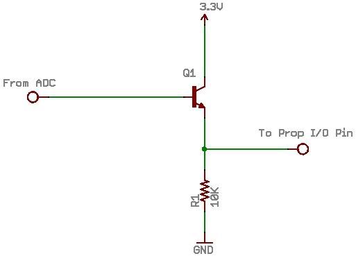
This is to interface a 16-bit ADC (MAX1179) to the Prop. This circuit will be replicated 16 times (one for each ADC output), so a low component count is necessary.
I need to verify that the design I'm using is correct and if not, what changes need to be made. This is what I vaguely remember from previous posts, but I'm not sure if this is what everyone agreed is correct or incorrect:
This is to interface a 16-bit ADC (MAX1179) to the Prop. This circuit will be replicated 16 times (one for each ADC output), so a low component count is necessary.
Comments
That will work but just a series resistor of about 1K or so does it also.
The thread re this is in the STICKY section...
cheers
Ron OZ
Awesome! This is going to be on a 4' x 3" double-sided board, so component space is at a premium. 16 additional components will be far easier to add than 32.
[noparse][[/noparse]edit]
I'm still going to need the pull-down resistors for the I/O pins, so I guess I'm still at 32...
[noparse][[/noparse]/edit]
So it is... I never thought to look there.
Consider using some of those resistor networks..
If you pulling 8 resistors to 0V you can buy of those 9 pin "resnets" that is only one tiny componets
Takes very little room...
see link as to what they may look like
http://www.bourns.com/components.aspx?cmsphid=7631383|7163299|3711038
cheers Ron OZ
Yes, I am aware of them. I just forgot about them. That will work.
As the 16 data lines are definitely tri-state you indeed ought to add pull-ups (e.g. 22k). It might prevent some unclear issues, although it will not be worse than unused Propeller pins kept in input mode (that's what everyone is doing, against all recommendations
The cleanest solution with 5V will be this:
                         +3V3
                           |
                          .-.
                          | | 22k pull-up
                          | |
                          '-'
                           |
            ADC --------|<---------- Propeller

                      diode

(created by AACircuit v1.28.6 beta 04/19/05 www.tech-chat.de)
Post Edited (deSilva) : 10/14/2007 10:14:24 PM GMT
@deSilva: All recommendations? I don't recall reading anything in the data sheet or manual about this. Please elaborate on what "all recommendations" means for the benefit of the readers of the thread.
▔▔▔▔▔▔▔▔▔▔▔▔▔▔▔▔▔▔▔▔▔▔▔▔
The more I know, the more I know I don't know.· Is this what they call Wisdom?
Post Edited (Ken Peterson) : 10/15/2007 1:42:02 AM GMT
So, a general recommendation for CMOS inputs is to tie them to ground when unused, with or without a resistor.
Second, if they happen to be I/O pins just make them outputs! This is extremely simple and costs nothing!
Right.