

SX 3 axis (soon to be 4 axis) CNC mill 0.0005 acurracy.
 Polywogs
Posts: 28
Polywogs
Posts: 28
60+ 16bit word var, 70+ 8bit byte var.
Source Code for SX in posts that follow. VB6 source code for hand shake control also follow. AutoCad widget for NC conversion included with VB6 source code.
Questions/comments to this thread. Typo's stay.
···· Radian CW and CCW, spiral cuts, linear, win32 interface through rs232 @ 38400 (may add blue tooth in the future), speed and position control of SX. Up to 4 inches per minute (alot faster even when performing circles if i had heat sinking on the stepper motor output transistors). Room in the memory for a 4th axis. THERE's NOTHING LIKE THE FIRST ONE. First test was a heart stopper.
··· Guenther Daubach·Your SX/B simulator works great. with it I could develope a Cordic Method that churns out very accurate integer circles very, very·fast.(Low processor overhead.)
·· Whats really cool is that the SX controller can handle comms between steps, meaning,·most of the SX48 controllers scan is just waiting for RS232 comms to handshake with, the time to resolve circlular position data or linear position between steps is small.
Post Edited (Polywogs) : 11/11/2007 11:30:44 AM GMT
350 x 263 - 14K
350 x 263 - 10K
Comments
Is your .0005" accuracy measured (which means it's actual accuracy) or theoretical? There's a lot more to getting 1/2 a thousandth accuracy than moving a stepper to a known location. The entire rest of the machine comes into play.
Thanks,
PeterM
Second is to reduce the speed(in a simulation a 1 would be good)
The motors are located at H8000 a home position.
A full circle is 62832 (radians would be 2 PI or 6.2832) and a max length is 62832 for a full circle.
example: a start angle of PI in a standard coordinate would be 180 degrees and a length of 62832 (2 PI = 360 degrees)
would rotate about an XY cordinate 2 PI radians (360 degrees) which is a full circle. The radius is circle size.
Load the desired values into the sDataVarB90 variables ( program shows the order )
Last fill in the ASCII code for the type of move in the 0 byte of sDataVarB90 and the 13 byte sDataVarB90, run it.
Play with the interupt to get the best simulation, takes time.
A linear move is the easiest. when the microcontroller finishes a move it transmits a move complete (Handshake).
38400 is the serial and a MAX232 5 volt is the converter. I've got the Z axis off revamping the mechanics.
How fast will it go?
1920 pulses = inch
·
This sounds cool. Do post more details! I would like to understand what you have done.
- Sparks
Copy that.
▔▔▔▔▔▔▔▔▔▔▔▔▔▔▔▔▔▔▔▔▔▔▔▔
- - - PLJack - - -
Perfection in design is not achieved when there is nothing left to add.
It is achieved when there is nothing left to take away.
··· Judge it good, judge it bad? You decide.
···· Included is a widget for AutoCad, it can be adapted to almost any cad (I have it where I work). With it one can convert selected parts of a drawing to NC. In its own right it has powers not seen in other cad systems including MasterCam. (AutoCad has VB system registries weakness in the ACadEntity and may have to be cleared once in a while.)
···· If you make a change or rewrite this code please·post a pointer here to your thread, I will then include your threads in my posts. This may code contain swearing in the lines due to a simple·and·frustrated mind with an obsesive behavoir vent (this).
···· A mechanical description when the Z axis is remounted. ( I have less than a hundred bucks in this thing excluding the programmer ).
I have been playing around with the prop chip to do something very similar - I don't have a machine for it to go on right now but that is but a minor detail.
Keep up the good work.
Andrew
There's a huge Yahoo forum on it, and it's pretty complete. It's free to try it out and play with the source code (in Pascal) is open to all who pay for the development. There's alot of add ons in the yahoo forum (encoder stuff, rpm control, ect)
Russ
I have been thinking of making a serial CNC controller for some time, but time always seems to get in the way of things.
I·have a couple of questions, (please excuse any dumb ones as I have never worked with the SX chip before).· I would like to make a control that is suitable for plasma or flame·cutting steel.· I would need to be able to cut at much higher speeds - in the 6000 to 10000mm per minute range.· I would·output standard step & direction pulses so that I could use external servo amps.
·So I guess my first question is; what is the limiting factor in regard to speed???· What do I need to look at to increase the step rates???
Would there be any advantage to using multiple SX chips ie. one for processing/parsing the serial input from the pc and then one for each axis to generate the steps. If I went this way how could I coordinate the multiple chips for interpolated moves, either linear or circular??
Have you played with the Propellor chip? Would they be a better device for this project???
Thanks for your help
Regards
Andrew
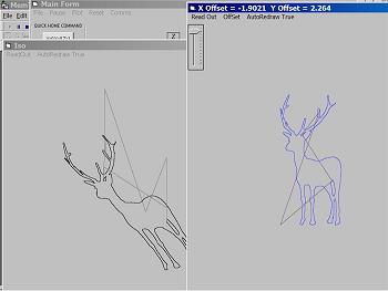
··· This machine I've built is just for hobby. I broke the arbor shaft while engraving a horse into wood so it must be repaired. I'm also rebuilding·new X and Y axis, beefing them up because they're single rails now. Tomorrow I'll try to include a photo of the machine, electronics, and some projects.
···· Right now the resolution is based on 1920 pulses per inch, in the vb code find all the 1920 conversions that are transmitted and change them to the resolution you need.
···· I lean toward electronics and must conclude that this, as a stepper project, will probably move to slow for plasma cutting, but the speed may be ok for fusion (plasma)·welding.
···· An idea I've been thinking about is switching up to a servo drive that allows quadrature input such as the Ultra 100 drive. Speed and heat would then not be a problem then but to turn a circle with the sx I used the Cordic method to buffer coordinates. As the source will show, the smaller the circle the more interations it takes to develope a new linear move. This was based on a thereom that in machining, small moves wouldn't be too small, and one·would lean toward cutter comp making radius around sharp edges no smaller than the tool diameter.
···· I'll post updated vb code shortly in a seperate message leaving the original.
···· Improvments:
········ Offset also adjusts output.
········ Size control also sizes output.
········ Quick home takes into account offset.
········ Code to convert shades to seperated bitmaps for coding to NC. Samples provided.
········ A position retrans for missed handshakes. (machine hanging)
·····To Do:
········ Offset hard entry form.
········
···· Facts:
········ This started as a parallel port project one pin on the sx was for clock and another pin for direction, per axis. Motion was lowsey at best, but it did work.
········ There are 72,·16 bit word variables used in the program 80+, 8 bit variables.
········ I tried to transmit a circle in streight lines over RS232 point by point, don't bother.
········ The first HP calculators that·had trig·functions relied on the Cordic method to resolve functions.
········ Memory was expensive leading to the development to Cordic method functions, as it became less expensive the method turned to·look up tables to free up the processor over head.
········ Now processors are getting so fast that the Cordic method is an alternative to a coprocessor call.
·
Thanks for sharing your code with us. I have been examining it and playing with it. I really like the simulation concept. Anytime I can quickly find out if something is likely to work or not before expending a lot of time building it is helpful.
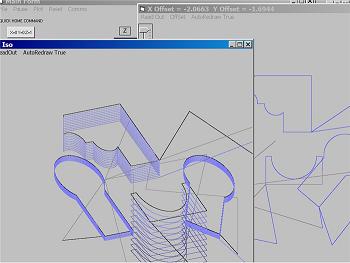
I am trying to test the circular functions. I know they work with the examples provided. However, I am trying to get the software to simulate the proper machining of a test part and the results are not what I expected.
A drawing of the test part is attached, as is an NC file I think should properly machine the part. I have also attached a view of the simulation output.
If you have time to look into this, I will appreciate any comments you might have. I like where you are going with this and am impressed that you are doing circular interpolation in real time on the SX. Keep up the good work!
- Sparks
P.S. I also receive a “G_Box Incorrect” error for G01 in “N035 G01 Y0.7395” but it allows me to continue.
Personally I think this could be adapted perhaps to run a sort of home made plotter with etch resist pens, so you can design a pcb, and have this draw all the traces ready for etching.
I have a Taig Mill that I use for ali and pcb prototyping already, but this could be very cool to run said plotter. I guess you could take a normal plotter and take out the electronics leaving only the motors and run them from your SX code, as I have found it difficult to do properly in HPGL
DJH
Included is Left and Right cutter comp with a cut depth of 0.5000".
Post Edited (Polywogs) : 11/11/2007 10:50:01 AM GMT
On your milling sample, I assume, "Brett" is the dog's name. As a matter of fact, in German language, "Brett" means "plank", so it also perfectly names the part you have used for milling (at least in German language)
▔▔▔▔▔▔▔▔▔▔▔▔▔▔▔▔▔▔▔▔▔▔▔▔
Greetings from Germany,
G
Thanks for taking time to address my question regarding the formatting and handling of arcs. If I understand correctly, your code is expecting the I, J, K arc coordinates to be absolute positions rather than relative positions. I think I can handle that all right. Of course, I can change it if I do not like it since you have made your source code available!
I took the AutoCAD drawing of the test part into work and generated an NC file using software that generates code for our huge CNC machine. Then I loaded the resulting NC file into your software. It did not run right away but after I removed all of the machine specific coding the software adds for our machine setup, tool selection and probing, etc. it ran just fine. Awesome!
So now I want to build an SX controlled CNC machine! Thanks for posting about this. I am excited about what you are doing.
- Sparks
P.S. Where can I read about the cordic method you are using? It seems there are a few cordic approaches out there. I would like to study the method you used to better understand your code. Thanks.
I renamed some of the variables to help to understand this subroutine
·
XY_CIRCLE: is the start of the Cordic Algorithm. The quadrant is changed to Quadrant I but whatever the quadrant your in is flagged·for restoration at the end of the subroutine.
·
The idea is to dither the current angle ADDING AND SUBTRACTING the Cordic data, the data in this case is "(2 PI Radians) * 10,000" for an integer value of 62832 which is my circle. It data is calculated in a manor that it is done in powers of two which fits into binary shifts.
·
Y = length of radius of the circle and X = 0
·
Y and X then follow the Cordic angle as it dithers. The result is a skewed and WILL be normalized. Fortunately it is a linear skew which is known as a Cordic Gain and is corrected by multiplying X Y by ** 39797 or (39797/65536)=0.6072540283203125 (The SX/B Program makes it so easy!)
·
Change in the program to allow reliable buffering at any InteruptCounter located @· Bank 12
In the simulator:
·
First, Toggle Pin D0 on and then start the simulator, stop when activity is only Bank 12, now change memory location at Bank 13 to &H02.
·
Second, set the controller to a new position of X = &H6000, Y = &H8000, Z = &H8000 by placing the following hex values into the received buffer starting at Bank 90;·· (5A), (00), (60), (00), (80), (00), (80), (00), (00), (00), (00), (00), (00), (5A) run the simulation then stop the only activity again is the InteruptCounter located @ Bank 12. The X = &H7000, Y = &H8000, Z = &H8000.
·
Last is to start a circular move around X = &H8000, Y = &H8000 from PI radians to 0 radians clockwise. Z will also move linear to the completed arc. From the halted simulation place the following hex values into the received buffer starting at &H90··· (4D), (00), (80), (00), (80), (70), (80), (00), (20), (B8), (7A), (B8), (7A), (4D), restart the simulator.
·
The Cordic subroutine will become active and the buffer should start filling with consecutive moves. The Interrupt will begin loading the buffers into the linear move subroutines and the motor data will change. Bank 40 - 45 will show the current position.
·
Again, the SerialIn is in the MAIN to avoid Interrupt waist, when the data packet is VALID, it will be handled during a normal scan of MAIN stripping the buffered data of the command. This is simply a modified SerialIn for an SX28. The Packets are 14 bytes down and 14 bytes returned in response. 14 bytes are also sent when the move is complete signal the computer to send the next move. At 38400, it’s fast and stripped down there may not be a need for a Cordic Method.
·
But…. A near project will involve sending a quadrature signal data for each of XYZ to servo amps to control position; Cordic will almost be a certain must.
Post Edited (Polywogs) : 11/17/2007 1:26:16 PM GMT
Features:
1. 24 bit words.
2. 48 bit multiply subroutine.
3. 48 bit divide subroutine
4. Subroutine calls from interrupt
5. A 20 iteration Cordic resolver that supplies both sine and cosine. (Does not include Quadrant resolver, add two more bits of definition to your circle!)
6. Real time serial communications @38400.
7. 3 Axis Cube root motion.
8. 4000 pulses per inch. That's 4194.30375 inches @ 0.000250 resolution.
9. So far the program is up to $D01 leaving 766 bytes left. The program has plenty of room for compression.
10. Gecko Drives with Automation Direct Stepper Motors are the primary movers this time.
SOON! Testing is almost complete. Source code to follow
Sounds great.· Keep up the good work and I look forward to seeing what you come up with.
Andrew