

Another RGB LED experiment - not long, with pictures.
 PLJack
Posts: 398
PLJack
Posts: 398
Color. There are many models for producing color.
For our purpose the RGB color model is the most important.
I've had some frustration producing color with RGB LED's. So I decided to do a weekend study and share it with you.
One would think that if we have a Red, Green and Blue LED that we could produce any color that we wanted. This is not the case.
LED's do not precisely follow the RGB color model. A lack of the color black is one of the culprits. (no, turning the room lights off won't work). In most color models black is used to produce saturation. Take the color Gray for instance. A computer monitor with RGB pixels can produce a gray color because black is the base color. A RGB LED will only be able to produce white. As you try to make darker gray's you just end up with a dimmer white. And it doesn't stop there. Many laws of color fall apart with RGB LED's.
So, just what colors can we produce with RGB LED's.
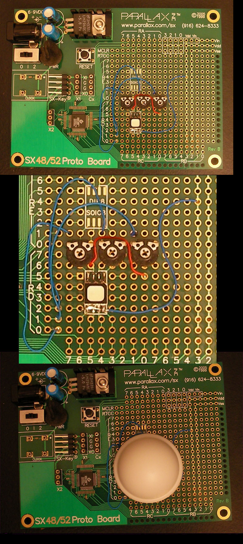
First we need a test unit. In this case I am using the Parallax SX 48 Proto board.
A Nichia NSSM016C RGB LED. (thanks StarMan). And three adjustable 1K resistors. I have found that it is convenient, although not practical, to use adjustable resistors in order to tune the LED for a perfect white color. Using standard resistors values is perfectly OK as well, but I find the final color will have a red or blue push to it. I am using PWM to reduce the amount of voltage each LED receives. Each LED can be set to a value between 0 to 255. At zero the LED is off. As the number climbs the LED gets brighter. 255 being full brightness. The SX/B code is attached to this thread.
Here is the test unit:

Notice the plastic dome covering the LED. With this on top of the LED we can get a nice defuse color. I spent more hours trying to get a "too smart for its britches" digital camera to take decent pictures than I did coding for the project. Just when I was ready to give up I remembered that I had a little dome AC night light. The plastic dome is perfect for this application. That and the discovery that I can tell my camera what to look at to decide its exposure time saved this project. The colors are somewhat inaccurate but you can still gauge the color reproduction of the LED.
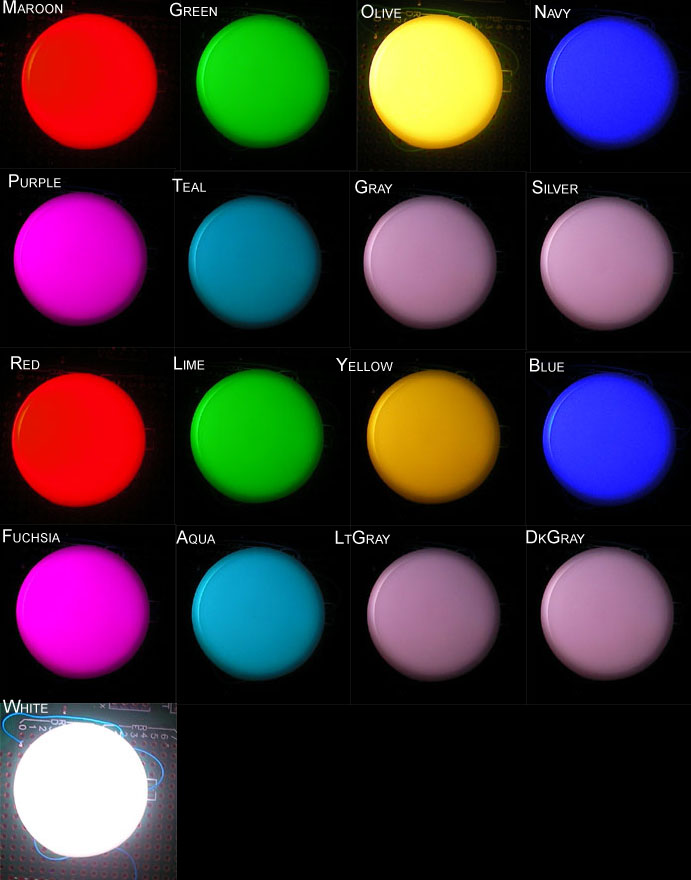
First, let's try the MS Windows system colors, just to see what happens. This palette consists of the following colors:
clBlack, clMaroon, clGreen, clOlive, clNavy, clPurple, clTeal, clGray, clSilver, clRed, clLime, clYellow, clBlue, clFushsia, clAqua, clLtGray, clDkGray and clWhite.
And performed it with this code:
Here are the results.

The colors that failed are Maroon, Olive, Navy, Teal, Gray, Silver, LtGray and DkGray.
Navy shows a blue. Teal as Aqua(Cyan) and of course all the grays are just dim whites.
Not too much of a surprise really.
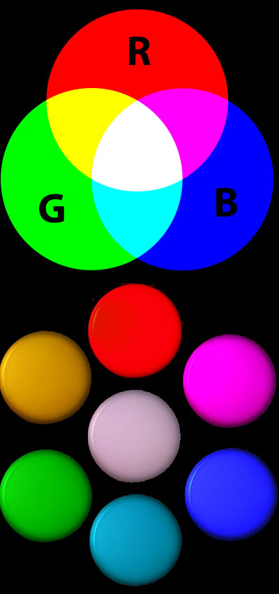
Next lets try the Additive Color palette. This is the basic RGB color model.
Let's start with red and move counterclockwise to white using this code:
Here are the results:

The camera under exposed yellow and white but the results are excellent. RGB LED's have no problem producing these seven colors. This is also not a surprise. All the RGB values are either 0 or 255. Simply a pure mix of the additive colors.
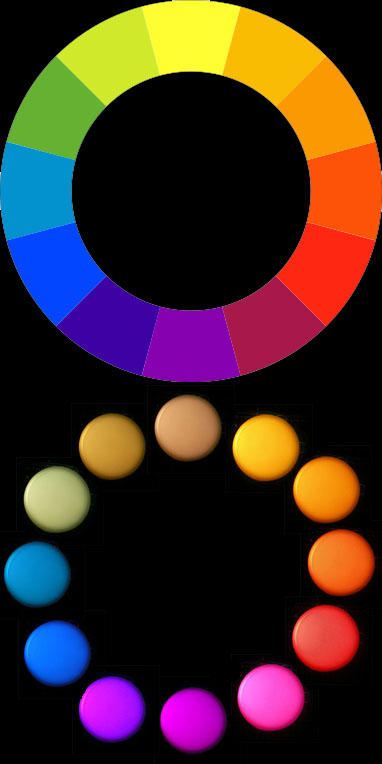
Now lets push RGB LED's way outside of their realm by trying to reproduce the Subtractive Color palette model. Our model will be the standard subtractive wheel.
The code:
The results:

Every color that is not close to the seven additive colors fail miserably.
Some are worse than others. The big surprise is the color on top of the wheel that appears to be yellow. The issue is that the RGB values of that color are (254-254-51). In additive color land that is not yellow (255-255-0). The end result is a "dead fish belly yellow".
So, there you have it. Download the code and have fun.
I would be interested in any results or theories you come up with. Mine are based on the observations of this experiment and not an exhaustive study.
NOTE: Small bug fix to code. Attached in next response.
▔▔▔▔▔▔▔▔▔▔▔▔▔▔▔▔▔▔▔▔▔▔▔▔
- - - PLJack - - -
Perfection in design is not achieved when there is nothing left to add.
It is achieved when there is nothing left to take away.
Post Edited (PLJack) : 10/1/2007 10:18:03 PM GMT
For our purpose the RGB color model is the most important.
I've had some frustration producing color with RGB LED's. So I decided to do a weekend study and share it with you.
One would think that if we have a Red, Green and Blue LED that we could produce any color that we wanted. This is not the case.
LED's do not precisely follow the RGB color model. A lack of the color black is one of the culprits. (no, turning the room lights off won't work). In most color models black is used to produce saturation. Take the color Gray for instance. A computer monitor with RGB pixels can produce a gray color because black is the base color. A RGB LED will only be able to produce white. As you try to make darker gray's you just end up with a dimmer white. And it doesn't stop there. Many laws of color fall apart with RGB LED's.
So, just what colors can we produce with RGB LED's.
First we need a test unit. In this case I am using the Parallax SX 48 Proto board.
A Nichia NSSM016C RGB LED. (thanks StarMan). And three adjustable 1K resistors. I have found that it is convenient, although not practical, to use adjustable resistors in order to tune the LED for a perfect white color. Using standard resistors values is perfectly OK as well, but I find the final color will have a red or blue push to it. I am using PWM to reduce the amount of voltage each LED receives. Each LED can be set to a value between 0 to 255. At zero the LED is off. As the number climbs the LED gets brighter. 255 being full brightness. The SX/B code is attached to this thread.
Here is the test unit:
Notice the plastic dome covering the LED. With this on top of the LED we can get a nice defuse color. I spent more hours trying to get a "too smart for its britches" digital camera to take decent pictures than I did coding for the project. Just when I was ready to give up I remembered that I had a little dome AC night light. The plastic dome is perfect for this application. That and the discovery that I can tell my camera what to look at to decide its exposure time saved this project. The colors are somewhat inaccurate but you can still gauge the color reproduction of the LED.
First, let's try the MS Windows system colors, just to see what happens. This palette consists of the following colors:
clBlack, clMaroon, clGreen, clOlive, clNavy, clPurple, clTeal, clGray, clSilver, clRed, clLime, clYellow, clBlue, clFushsia, clAqua, clLtGray, clDkGray and clWhite.
And performed it with this code:
'__________________________________________________________
'
' S_CycleSystemColor            SUB     0
' Simply cycles the pseudo system colors.
'__________________________________________________________
S_CycleSystemColors:

FOR UtilVar = 0 TO clSysColorMax
        READ D_SystemRed        + UtilVar, RedVal
        READ D_SystemGreen      + UtilVar, GreenVal
        READ D_SystemBlue       + UtilVar, BlueVal
        PAUSE LongDelay

NEXT
RETURN
'==========================================================
Here are the results.
The colors that failed are Maroon, Olive, Navy, Teal, Gray, Silver, LtGray and DkGray.
Navy shows a blue. Teal as Aqua(Cyan) and of course all the grays are just dim whites.
Not too much of a surprise really.
Next lets try the Additive Color palette. This is the basic RGB color model.
Let's start with red and move counterclockwise to white using this code:
'__________________________________________________________
'
' S_CyclePrimaries              SUB     0
' Cycles the primary additive colors.
' http://en.wikipedia.org/wiki/RGB
'__________________________________________________________
S_CyclePrimaries:

S_RGB 255, 0, 0         'RED
PAUSE LongDelay
S_RGB 255, 255, 0       'Yellow
PAUSE LongDelay
S_RGB 0, 255, 0         'Green
PAUSE LongDelay
S_RGB 0, 255, 255       'Cyan
PAUSE LongDelay
S_RGB 0, 0, 255         'Blue
PAUSE LongDelay
S_RGB 255, 0, 255       'Purple
PAUSE LongDelay
S_RGB 255, 255, 255     'White
PAUSE LongDelay

RETURN
'==========================================================
Here are the results:
The camera under exposed yellow and white but the results are excellent. RGB LED's have no problem producing these seven colors. This is also not a surprise. All the RGB values are either 0 or 255. Simply a pure mix of the additive colors.
Now lets push RGB LED's way outside of their realm by trying to reproduce the Subtractive Color palette model. Our model will be the standard subtractive wheel.
The code:
'__________________________________________________________
'
' S_CycleSubtractivePrimaries       SUB     0
' Cycles the subtractive primary colors.
' http://en.wikipedia.org/wiki/Subtractive_color
'__________________________________________________________
S_CycleSubtractivePrimaries:

FOR UtilVar = 0 TO SubtractiveMax
        READ D_SubtractivePrimaryRed    + UtilVar, RedVal
        READ D_SubtractivePrimaryGreen  + UtilVar, GreenVal
        READ D_SubtractivePrimaryBlue   + UtilVar, BlueVal
        PAUSE LongDelay
NEXT
RETURN
'==========================================================
The results:
Every color that is not close to the seven additive colors fail miserably.
Some are worse than others. The big surprise is the color on top of the wheel that appears to be yellow. The issue is that the RGB values of that color are (254-254-51). In additive color land that is not yellow (255-255-0). The end result is a "dead fish belly yellow".
So, there you have it. Download the code and have fun.
I would be interested in any results or theories you come up with. Mine are based on the observations of this experiment and not an exhaustive study.
NOTE: Small bug fix to code. Attached in next response.
▔▔▔▔▔▔▔▔▔▔▔▔▔▔▔▔▔▔▔▔▔▔▔▔
- - - PLJack - - -
Perfection in design is not achieved when there is nothing left to add.
It is achieved when there is nothing left to take away.
Post Edited (PLJack) : 10/1/2007 10:18:03 PM GMT

Comments
-Phil
' =========================================================
'
'   File...... RGBColors.sxb
'   Purpose... Demonstrate RGB Color Models
'   Author.... Jack Kelly (PLJack)
'   E-mail....
'   Started... Sept 21, 2007
'   Updated... Sept 23, 2007
'
' =========================================================


' ---------------------------------------------------------
' Device Settings
' ---------------------------------------------------------
DEVICE SX48, OSC4MHZ
'DEVICE SX28, OSC4MHZ, TURBO, STACKX, OPTIONX
FREQ 4_000_000

' ---------------------------------------------------------
' IO Pins
' ---------------------------------------------------------
PWM_R    PIN RD.0 OUTPUT  ' Red LED Pin
PWM_G    PIN RD.1 OUTPUT  ' Green LED Pin
PWM_B    PIN RD.2 OUTPUT  ' Blue LED Pin

' ---------------------------------------------------------
' Constants
' ---------------------------------------------------------
'--- Common Anode
LEDOn           con     0
LEDOff          con     1

'--- Common Cathode
'LEDOn          con     1
'LEDOff         con     0

'--- MS Windows system colors.
clSysColorMax   CON 17
SubtractiveMax  CON 12
clBlack         CON 0
clMaroon        CON 1
clGreen         CON 2
clOlive         CON 3
clNavy          CON 4
clPurple        CON 5
clTeal          CON 6
clGray          CON 7
clSilver        CON 8
clRed           CON 9
clLime          CON 10
clYellow        CON 11
clBlue          CON 12
clFuchsia       CON 13
clAqua          CON 14
clLtGray        CON 15
clDkGray        CON 16
clWhite         CON 17

'--- Used for loop delays and pausing in general
FastDelay       CON 15
ShortDelay      CON 500
LongDelay       CON 1000

' ---------------------------------------------------------
' Variables
' ---------------------------------------------------------

PwmCounter      var     Byte    '--- Controls voltage to
                                '--- LEDs via the
                                '--- INTERRUPT routine.

RedVal          var     Byte    '--- RGB values
GreenVal        var     Byte    '--- 0 is off.
BlueVal         var     Byte    '--- 255 IS FULL ON

UtilVar         var     Byte    '--- Used for loops.

' ---------------------------------------------------------
INTERRUPT 25000         '--- Adjusted up until LED stopped
                        '--- blinking. Feel free to change
                        '--- it to your liking.
' ---------------------------------------------------------
 ISR_Start:

        Inc PwmCounter  '--- Add one to pwm counter.
                        '--- Note: it rolls over to 0 at 255.


        if PwmCounter = 0 then  '--- If a led value, RedVal
                Inc PwmCounter  '--- for  example, is zero
        endif                   '--- we want the led to
                                '--- receive no voltage.
                                '--- So, if PwmCounter is
                                '--- zero we add one to it
                                '--- so that it will  pass
                                '--- the IF statement below

        '--- Red LED PWM
        if PwmCounter > RedVal then
                PWM_R = LEDOff
        else
                PWM_R = LEDOn
        endif

        '--- Green LED PWM
        if PwmCounter > GreenVal then
                PWM_G = LEDOff
        else
                PWM_G = LEDOn
        endif

        '--- Blue LED PWM
        if PwmCounter > BlueVal then
                PWM_B  = LEDOff
        else
                PWM_B = LEDOn
        endif

ISR_Exit:
RETURNINT

' ---------------------------------------------------------
' Declare Subroutines
' ---------------------------------------------------------

S_Calibration                   SUB     0
S_RGB                           SUB     3
S_SystemColor                   SUB     1
S_CyclePrimaries                SUB     0
S_CycleSystemColors             SUB     0
S_CycleSubtractivePrimaries     SUB     0

S_MixPrimaries                  SUB     0

RampRed                         SUB     0
SlideRed                        SUB     0
RampGreen                       SUB     0
SlideGreen                      SUB     0
RampBlue                        SUB     0
SlideBlue                       SUB     0
Blink                           SUB     0


' ---------------------------------------------------------
' Program Code
' ---------------------------------------------------------

PROGRAM Start

Watch RedVal
watch GreenVal
watch BlueVal

Start:

S_RGB 0, 0, 0                   '--- Turn all LEDs off.

' #########################################################
' Main
' #########################################################

Main:

'S_Calibration                  '--- Used to calibrate LEDs
'GOTO Main                      '--- See S_Calibration func

'S_CycleSystemColors            '--- Uncomment to enable
'Blink                          '--- ...
'S_CyclePrimaries               '--- Uncomment to enable
'Blink                          '--- ...
'S_CycleSubtractivePrimaries    '--- Uncomment to enable
'Blink                          '--- ...
S_MixPrimaries

GOTO Main


' ---------------------------------------------------------
' Subroutine Code
' ---------------------------------------------------------

'__________________________________________________________
'
' S_Calibration:
' I used adjustable POTs on my RGB LED. I let this function
' run as I turn the POT on each LED.
' Once I have a nice white color I disable this function.
'__________________________________________________________

S_Calibration:

FOR UtilVar = 0 TO 255
        S_RGB UtilVar, UtilVar, UtilVar
        PAUSE 20
NEXT

S_RGB 128, 128, 128
PAUSE 5000

RETURN
'==========================================================

'__________________________________________________________
'
' S_RGB                           SUB     3
' Simply transfers the three parameters to the RGB Values.
'__________________________________________________________
S_RGB:

RedVal =        __PARAM1
GreenVal =      __PARAM2
BlueVal =       __PARAM3

RETURN
'==========================================================

'__________________________________________________________
'
' S_SystemColor                   SUB     1
' Recreates the standard MS Windows system colors.
' Pass this function one of the clColor constants
' listed above.
'__________________________________________________________
S_SystemColor:
        READ D_SystemRed        + __PARAM1, RedVal
        READ D_SystemGreen      + __PARAM1, GreenVal
        READ D_SystemBlue       + __PARAM1, BlueVal
RETURN
'==========================================================

'__________________________________________________________
'
' S_CycleSystemColor            SUB     0
' Simply cycles the pseudo system colors.
'__________________________________________________________
S_CycleSystemColors:

FOR UtilVar = 0 TO clSysColorMax
        READ D_SystemRed        + UtilVar, RedVal
        READ D_SystemGreen      + UtilVar, GreenVal
        READ D_SystemBlue       + UtilVar, BlueVal
        PAUSE LongDelay

NEXT
RETURN
'==========================================================

'__________________________________________________________
'
' S_CyclePrimaries              SUB     0
' Cycles the primary additive colors.
' http://en.wikipedia.org/wiki/RGB
'__________________________________________________________
S_CyclePrimaries:

S_RGB 255, 0, 0         'RED
PAUSE LongDelay
S_RGB 255, 255, 0       'Yellow
PAUSE LongDelay
S_RGB 0, 255, 0         'Green
PAUSE LongDelay
S_RGB 0, 255, 255       'Cyan
PAUSE LongDelay
S_RGB 0, 0, 255         'Blue
PAUSE LongDelay
S_RGB 255, 0, 255       'Purple
PAUSE LongDelay
S_RGB 255, 255, 255     'White
PAUSE LongDelay

RETURN
'==========================================================

'__________________________________________________________
'
' S_CycleSubtractivePrimaries       SUB     0
' Cycles the subtractive primary colors.
' http://en.wikipedia.org/wiki/Subtractive_color
'__________________________________________________________
S_CycleSubtractivePrimaries:

FOR UtilVar = 0 TO SubtractiveMax
        READ D_SubtractivePrimaryRed    + UtilVar, RedVal
        READ D_SubtractivePrimaryGreen  + UtilVar, GreenVal
        READ D_SubtractivePrimaryBlue   + UtilVar, BlueVal
        PAUSE LongDelay
NEXT
RETURN
'==========================================================


'__________________________________________________________
'
' S_CycleRGB                    SUB     0
' This will transverse through all possible
' color combinations.
'__________________________________________________________

S_MixPrimaries:

RampRed
PAUSE ShortDelay
RampGreen
PAUSE ShortDelay
SlideRed
PAUSE ShortDelay
RampBlue
PAUSE ShortDelay
SlideGreen
PAUSE ShortDelay
RampRed
PAUSE ShortDelay
SlideBlue
PAUSE ShortDelay
SlideRed
PAUSE ShortDelay

RETURN

'==========================================================


'__________________________________________________________
'
' RampRed                        SUB     0
' From dim to bright.
'__________________________________________________________
RampRed:

FOR UtilVar = 0 TO 255
        IF RedVal < 255 then
                INC RedVal
        ENDIF
PAUSE FastDelay
NEXT
RETURN
'==========================================================

'__________________________________________________________
'
' SlideRed                       SUB     0
' Bright to dim.
'__________________________________________________________
SlideRed:

FOR UtilVar = 0 TO 255
        IF RedVal > 0 then
                DEC RedVal
        ENDIF
PAUSE FastDelay
NEXT
RETURN
'==========================================================

'__________________________________________________________
'
' RampGreen                      SUB     0
' From dim to bright.
'__________________________________________________________
RampGreen:

FOR UtilVar = 0 TO 255
        IF GreenVal < 255 then
                INC GreenVal
        ENDIF
PAUSE FastDelay
NEXT
RETURN
'==========================================================

'__________________________________________________________
'
' SlideGreen                     SUB     0
' Bright to dim.
'__________________________________________________________
SlideGreen:

FOR UtilVar = 0 TO 255
        IF GreenVal > 0 then
                DEC GreenVal
        ENDIF
PAUSE FastDelay
NEXT
RETURN
'==========================================================
'__________________________________________________________
'
' RampBlue                       SUB     0
' From dim to bright.
'__________________________________________________________
RampBlue:

FOR UtilVar = 0 TO 255
        IF BlueVal < 255 then
                INC BlueVal
        ENDIF
PAUSE FastDelay
NEXT
RETURN
'==========================================================

'__________________________________________________________
'
' SlideBlue                      SUB     0
' Bright to dim.
'__________________________________________________________
SlideBlue:

FOR UtilVar = 0 TO 255
        IF BlueVal > 0 then
                DEC BlueVal
        ENDIF
PAUSE FastDelay
NEXT
RETURN
'==========================================================


'__________________________________________________________
'
' Blink                         SUB     0
' Just a blink that we can reconize.
'__________________________________________________________

Blink:

S_RGB 0,0,0
PAUSE ShortDelay
S_RGB 255,0,0
PAUSE ShortDelay
S_RGB 0,0,0
PAUSE ShortDelay
S_RGB 0,0,255
PAUSE ShortDelay
S_RGB 0,0,0


RETURN


' DATA statement for color models.
D_SystemRED:
DATA    0
DATA    128
DATA    0
DATA    128
DATA    0
DATA    128
DATA    0
DATA    128
DATA    192
DATA    255
DATA    0
DATA    255
DATA    0
DATA    255
DATA    0
DATA    192
DATA    128
DATA    255

D_SystemGreen:
DATA     0
DATA     0
DATA     128
DATA     128
DATA     0
DATA     0
DATA     128
DATA     128
DATA     192
DATA     0
DATA     255
DATA     255
DATA     0
DATA     0
DATA     255
DATA     192
DATA     128
DATA     255

D_SystemBlue:
DATA     0
DATA     0
DATA     0
DATA     0
DATA     128
DATA     128
DATA     128
DATA     128
DATA     192
DATA     0
DATA     0
DATA     0
DATA     255
DATA     255
DATA     255
DATA     192
DATA     128
DATA     255


D_SubtractivePrimaryRed:
DATA    254
DATA    250
DATA    251
DATA    253
DATA    254
DATA    167
DATA    134
DATA    61
DATA    2
DATA    3
DATA    102
DATA    208

D_SubtractivePrimaryGreen:
DATA    254
DATA    188
DATA    153
DATA    83
DATA    39
DATA    25
DATA    1
DATA    1
DATA    71
DATA    146
DATA    176
DATA    234

D_SubtractivePrimaryBlue:
DATA    51
DATA    2
DATA    2
DATA    8
DATA    18
DATA    75
DATA    175
DATA    164
DATA    254
DATA    206
DATA    50
DATA    43
▔▔▔▔▔▔▔▔▔▔▔▔▔▔▔▔▔▔▔▔▔▔▔▔
- - - PLJack - - -
Perfection in design is not achieved when there is nothing left to add.
It is achieved when there is nothing left to take away.
Hey, that looks handy.
$5.60 a pop though. I can think of allot of applications for that.
Thanks.
BTW: The camera did a mediocre job at reproduction. The colors look beautiful on the bench.
▔▔▔▔▔▔▔▔▔▔▔▔▔▔▔▔▔▔▔▔▔▔▔▔
- - - PLJack - - -
Perfection in design is not achieved when there is nothing left to add.
It is achieved when there is nothing left to take away.
I would like to try this on my 8x8 RGB Led matrix (one RGB Led set first) and then maybe expand it out.
It looks like you used potentiometers for current limiting resistors in your SX-48 pics. Do you have any connection schematics? Or at least tell me what value resistors to use? I'm thinking 220 - 470 ohms until I get into moving displays and then it would be less resistance for better brightness due to the lower duty cycle of LED on time.
Very neat!
Any LED driver calculator will work to get your values.
such as this one. LED calculator
As for my pots, they are 0 to 1K pots. I don't know the exact values that are currently set to.
Roughly 30 to 35%. I could have gone lower but its not good to stare at a bright LED for two days.
▔▔▔▔▔▔▔▔▔▔▔▔▔▔▔▔▔▔▔▔▔▔▔▔
- - - PLJack - - -
Perfection in design is not achieved when there is nothing left to add.
It is achieved when there is nothing left to take away.
That's a good thing.
My work is done here.
▔▔▔▔▔▔▔▔▔▔▔▔▔▔▔▔▔▔▔▔▔▔▔▔
- - - PLJack - - -
Perfection in design is not achieved when there is nothing left to add.
It is achieved when there is nothing left to take away.
Thanks...
I looked through my old orders, did not see it.
I'm pretty sure I bought it via Ebay from a use of these forums called StarMan.
I can highly recommend these ones though:
www.mouser.com/Search/ProductDetail.aspx?R=AAF5060PBESEEVGvirtualkey60400000virtualkey604-AAF5060-RGB
www.mouser.com/Search/ProductDetail.aspx?R=OVSARGB3R8virtualkey54210000virtualkey828-OVSARGB3R8
▔▔▔▔▔▔▔▔▔▔▔▔▔▔▔▔▔▔▔▔▔▔▔▔
- - - PLJack - - -
Perfection in design is not achieved when there is nothing left to add.
It is achieved when there is nothing left to take away.
Do you think using an LED driver (instead of the SX outputs) would change anything? I have a RGB LED surface mounted to a new product for Brilldea that includes an Allegro Microsystems A6281 constant current LED driver. This IC has three channels and each channel has 10-bit control as well as dot correction control. Check out the IC here: http://www.allegromicro.com/en/Products/Part_Numbers/6281/index.asp
If you are interested in this device I can post pictures tomorrow and send you one or two by post for testing. I have some very rudimentary code written for the Propeller to control this product, but nothing for the SX. In the coming week I will be writing a complete driver for the Propeller.
You said you used PWM for your control at 8-bits resolution. Is there any advantage (beside reducing processing overhead) to using a BAM method (bit amplitude angle modulation)? You might be able to increase the resolution also with this method.
▔▔▔▔▔▔▔▔▔▔▔▔▔▔▔▔▔▔▔▔▔▔▔▔
Timothy D. Swieter, E.I.
www.brilldea.com - Prop Blade, LED Painter, RGB LEDs, 3.0" LCD Composite video display, eProto for SunSPOT
www.tdswieter.com
Post Edited (Timothy D. Swieter) : 3/29/2009 2:05:38 PM GMT
What is BAM? Google has nothing on it as it is a first for my ears.
Thanks.
▔▔▔▔▔▔▔▔▔▔▔▔▔▔▔▔▔▔▔▔▔▔▔▔
Tom Smykowski: Well-well look. I already told you: I deal with the customers so the engineers don't have to. I have people skills; I am good at dealing with people. Can't you understand that? What is wrong with you people?
BAM is a method of intensity control for LEDs published by Artistic Licence. The basics is that you define a bit period and a your resolution. Let's say the bit period is x and the resolution is 8 bits. If the first bit is on, then the output is one for x time. If the second bit is on, then the output is on for 2x and so on. This is probably over simplified. There are couple app notes/resources on Artistic Licence web site. The BAM method and publishing was done to combat certain companies in the LED lighting industry who were patenting everything - including PWM control of RGB LEDs! (lets not go there and take this thread off topic)
Web site: www.artisticlicence.com/
App Note: www.artisticlicence.com/WebSiteMaster/App%20Notes/appnote011.pdf
I plan on writing a Propeller driver for another product I have nearly finished in hardware design that will use the BAM method of intensity control. I believe there are also a few posts on the web with PIC and AVR projects using BAM.
▔▔▔▔▔▔▔▔▔▔▔▔▔▔▔▔▔▔▔▔▔▔▔▔
Timothy D. Swieter, E.I.
www.brilldea.com - Prop Blade, LED Painter, RGB LEDs, 3.0" LCD Composite video display, eProto for SunSPOT
www.tdswieter.com
Can you help me understand how the data statements for the color models were arrived at? This may be a stupid question but I would appreciate if I find out the logic behind it.
Thanks.
Danny
· Here is a BAM implementation for the SX.
· Sorry about all the comments·
·Bean
' Bit Angle Modulation
'
DEVICE SX28,OSC4MHZ
FREQ 4_000_000

LED      PIN RB.7 OUTPUT


pwmValue VAR BYTE

' Interrupt variables
bamBit   VAR BYTE
intTemp  VAR BYTE

INTERRUPT NOPRESERVE
  bamBit = bamBit >> 1
  IF bamBit = 0 THEN
    bamBit = 128
  ENDIF
  intTemp = pwmValue AND bamBit
  IF intTemp <> 0 THEN
    LED = 1
  ELSE
    LED = 0
  ENDIF
RETURNINT bamBit

PROGRAM Start NOSTARTUP

Start:
  bamBit = 1
  OPTION = %1000_0101 ' Prescale 64:1 = 244Hz update rate (Prescaler must be > cycles used in the interrupt)
  DO
    FOR pwmValue = 0 TO 255 STEP 15
      PAUSE 50
    NEXT
    FOR pwmValue = 255 TO 0 STEP -15
      PAUSE 50
    NEXT
  LOOP
END
▔▔▔▔▔▔▔▔▔▔▔▔▔▔▔▔▔▔▔▔▔▔▔▔
- - - - - - - - - - - - - - - - - - - - - - - - - - - - - - -
There is a fine line between arrogance and confidence. Make sure you don't cross it...
·
Hi Danny.
The DATA statements hold the RGB color values for each color model examined.
For example, The first four colors in the Windows system color model are clBlack, clMaroon, clGreen, clOlive.
Like so.
D_SystemRED:
DATA 0
DATA 128
DATA 0
DATA 128
D_SystemGreen:
DATA 0
DATA 0
DATA 128
DATA 128
D_SystemBlue:
DATA 0
DATA 0
DATA 0
DATA 0
The first value from each of the list above is 0, 0, 0. Black, ie: all leds off.
The second value from each is 128, 0, 0. Which is Maroon (Red at half brightness).
Third from each is 0, 128, 0, Green (at half brightness) Full green, 254, is actually defined as Lime
The numbers come from the RGB values defined in the Windows system pallet.
Then we just cycle through the colors:
FOR UtilVar = 0 TO clSysColorMax
READ D_SystemRed + UtilVar, RedVal
READ D_SystemGreen + UtilVar, GreenVal
READ D_SystemBlue + UtilVar, BlueVal
PAUSE LongDelay
NEXT
clSysColorMax is defined as 17 because there are 18 colors listed in each of the D_SystemX data statements.
Hope that helps.
Jack
▔▔▔▔▔▔▔▔▔▔▔▔▔▔▔▔▔▔▔▔▔▔▔▔
- - - PLJack - - -
Perfection in design is not achieved when there is nothing left to add.
It is achieved when there is nothing left to take away.
I know, late reply from me. That's not news[noparse]:)[/noparse]
Just read up on BAM. Pretty cool stuff.
As for increasing resolution it's been my experience that 8 bits is too much as it is.
Your eye will not notice 256 levels of brightness on an LED.
For RGB LEDs I'm would say that 4 bit is plenty (16 levels of brightness). 6 bit (64 levels) is definitely more that the beholder will be able to make out.
Just thought I would mention that.
Jack
▔▔▔▔▔▔▔▔▔▔▔▔▔▔▔▔▔▔▔▔▔▔▔▔
- - - PLJack - - -
Perfection in design is not achieved when there is nothing left to add.
It is achieved when there is nothing left to take away.
Yes, thanks for that Bean.
I'm currently trying to write code to run a 5x7 LED matrix that will have 8 shades of gray (brightness).
In other words I need to PWM each led, as opposed to cycling each column.
Not sure how but I see something useful in that example.
BTW, the STEP command had me confused. Never used it before.
How did I miss such a useful command?
Thanks
Jack
▔▔▔▔▔▔▔▔▔▔▔▔▔▔▔▔▔▔▔▔▔▔▔▔
- - - PLJack - - -
Perfection in design is not achieved when there is nothing left to add.
It is achieved when there is nothing left to take away.
The datasheet for the RGB LED you're using contains a graph of the colorspace of the three LEDs.· The graph is shown below.· The curve drawn in the graph represents the spectral colors we can see from red (longest wavelength) to blue (shortest wavelength).· The human eye can perceive all of the colors contained within the spectral curve.· The three LEDs are located near the red, green and blue spectral colors.· I added the red triangle, which shows the colorspace that the three LEDs can produce.· Only the colors within the interior of the triangle can be produced by a combination of the three LEDs.· There is a large area between green and blue that cannot be represented by the LEDs.
The LEDs should be able to produce a wide range of grays.· The color gray sits within the area of the triangle.· As you mentioned, it is not possible to produce black with the lights on.· The surface of the device looks white (or close to white) when ambient light shines on it.· You would have to shield the device from ambient light to be able to produce black.· The reflected light will combine with the generated light, and reduce the color saturation of the generated light.
Dave
Bean -- I have a question about your SX implementation.
I *think*, in my reading of the BAM appNote, that each bit position, if "on", results in a portion of the pulse being high, with the length *of that portion* depending on the bit position. In my reading of your code, each high bit results in an equal "portion" of the pulse being on???
So a 1 in bit.0 adds 39us (1x unit) to the pulse, a 1 in bit.1 adds 78us (2x unit). It seems in your code this wouldn't be the case? I.E. I should get 128x unit added to the pulse for a bit7 = 1.
Or am I missing something simple here???
Wouldn't there need to be something to scale the interrupt period before choosing to shift the bamBit mask? e.g.
INTERRUPT NOPRESERVE

DEC bamAccum
IF bamAccum = 0 THEN
   bamAccum = bamBit ' mult. of 2 cycles
   bamBit = bamBit >> 1
   IF bamBit = 0 THEN
      bamBit = 128
   ENDIF
   intTemp = pwmValue AND bamBit
   IF intTemp <> 0 THEN
      LED = 1
   ELSE
      LED = 0
   ENDIF
ENDIF
RETURNINT
Which would also seem to fit in better with the notion that the actual parsing of the PWM value and move to output happens much more infrequently then in "normal" PWM.
???
▔▔▔▔▔▔▔▔▔▔▔▔▔▔▔▔▔▔▔▔▔▔▔▔
When the going gets weird, the weird turn pro. -- HST
1uffakind.com/robots/povBitMapBuilder.php
1uffakind.com/robots/resistorLadder.php
Post Edited (Zoot) : 4/16/2009 12:48:27 PM GMT
· Notice at the end of the interrupt is "RETURNINT bamBit". bamBit will be 128 for the MSB, then 64, then 32, etc. So the MSB will last 128 times longer than the LSB. This is why the precaler must be set higher than the cycles used in the interrupt, because the LSB is effectively "RETURNINT 1".
· The whole idea of BAM is to NOT generate all those interrupts. In my implementation the interrupt code is only executed 8 times for each complete cycle.
· If you have periodic interrupts, you might as well just use PWM.
· Again,·appologies for not putting comments in the code. I'll update it ASAP.
Bean.
▔▔▔▔▔▔▔▔▔▔▔▔▔▔▔▔▔▔▔▔▔▔▔▔
- - - - - - - - - - - - - - - - - - - - - - - - - - - - - - -
There is a fine line between arrogance and confidence. Make sure you don't cross it...
Post Edited (Bean (Hitt Consulting)) : 4/16/2009 11:40:14 AM GMT
▔▔▔▔▔▔▔▔▔▔▔▔▔▔▔▔▔▔▔▔▔▔▔▔
When the going gets weird, the weird turn pro. -- HST
1uffakind.com/robots/povBitMapBuilder.php
1uffakind.com/robots/resistorLadder.php