

Reducing a circuit as small as possible?
 Morrolan
Posts: 98
Morrolan
Posts: 98
Hi guys,
I've recently got back into electronics after a 10 year gap - I'm now trying to turn my attention towards a small project, and by small, I mean smallest physical size that I can manage...
Without building a stamp myself from a kit, (that can wait for version 2!) I've trying to create a circuit in the smallest physical package that I can.
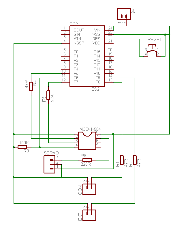
The circuit contains:
1 BASIC Stamp 2
1 8-pin IC
6 resistors
1 PCB mount tactile switch
2x header pins for switch 1 (called CON in schematic)
2x header pins for switch 2 (called EXT in schematic)
2x header pins for 9v supply (battery)
3x header pins for servo
The attached image will make it clearer.
NOTE: The pins will ultimately be soldered in at 90 degrees to the board so that the pins stick out sideways, not upwards - I just can't find it in the Eagle library yet.
And now to my questions -
How small can I make my traces? I'm using eagle, and setting the autoroute routing grid to 10 (it was in an eagle tutorial) from the default 50, and the traces look miniscule?
Also, how much gap should I leave between traces?
How close should the pins be for a standard 1/4W resistor (2.54mm, 5 mm?) Is it possible to use smaller physical resistors in the circuit without going as far as SMT components?
How safe is it to solder a BS2 direct to a PCB without a socket?
The board will be professionally made by a company called Eurocircuits - they are excellent within the EU (RoHS compliance stops me importing most hobby-boards from the US) and they also do a service for hobbyists at www.thepcbshop.com - including full soldermask and silkscreening. Sorry for the plug, but they seem to be the best available within the UK, and I'm sure I'm not the only stamp user in the UK!
My questions might seem a bit newbish, but it's been so long that I've forgotten so much!
Many thanks in advance,
Morrolan
▔▔▔▔▔▔▔▔▔▔▔▔▔▔▔▔▔▔▔▔▔▔▔▔
Flying is simple. You just throw yourself at the ground and miss.
I've recently got back into electronics after a 10 year gap - I'm now trying to turn my attention towards a small project, and by small, I mean smallest physical size that I can manage...
Without building a stamp myself from a kit, (that can wait for version 2!) I've trying to create a circuit in the smallest physical package that I can.
The circuit contains:
1 BASIC Stamp 2
1 8-pin IC
6 resistors
1 PCB mount tactile switch
2x header pins for switch 1 (called CON in schematic)
2x header pins for switch 2 (called EXT in schematic)
2x header pins for 9v supply (battery)
3x header pins for servo
The attached image will make it clearer.
NOTE: The pins will ultimately be soldered in at 90 degrees to the board so that the pins stick out sideways, not upwards - I just can't find it in the Eagle library yet.
And now to my questions -
How small can I make my traces? I'm using eagle, and setting the autoroute routing grid to 10 (it was in an eagle tutorial) from the default 50, and the traces look miniscule?
Also, how much gap should I leave between traces?
How close should the pins be for a standard 1/4W resistor (2.54mm, 5 mm?) Is it possible to use smaller physical resistors in the circuit without going as far as SMT components?
How safe is it to solder a BS2 direct to a PCB without a socket?
The board will be professionally made by a company called Eurocircuits - they are excellent within the EU (RoHS compliance stops me importing most hobby-boards from the US) and they also do a service for hobbyists at www.thepcbshop.com - including full soldermask and silkscreening. Sorry for the plug, but they seem to be the best available within the UK, and I'm sure I'm not the only stamp user in the UK!
My questions might seem a bit newbish, but it's been so long that I've forgotten so much!
Many thanks in advance,
Morrolan
▔▔▔▔▔▔▔▔▔▔▔▔▔▔▔▔▔▔▔▔▔▔▔▔
Flying is simple. You just throw yourself at the ground and miss.
614 x 783 - 24K
Comments
connectors and switches that could be placed in a nice·SIP style row alongside the BS2.
·
One thing I noticed right off... you might want to double check your wiring.· ...the servo connections 1 & 2 in your schematic are both VSS.
·
▔▔▔▔▔▔▔▔▔▔▔▔▔▔▔▔▔▔▔▔▔▔▔▔
Beau Schwabe
IC Layout Engineer
Parallax, Inc.
Try approaching it as making the traces as large as possible and still fit the need to be compact. This will make manual construction much easier.
Generally, this means I need a width that will just fit between two adjacent IC pads.
Using #16 on the wire size seems to work well for me. Of course I usually make the power lines more hefty and I often flood unused areas with copper fill as ground plane.
Regarding resistors, Eagle gives you dozens of options. It seems to be overkill.· I have 3 basic choices - 1/4 watt, 1/8 watt, and largest surface mount.· You don't really need 1/4 for 99% of IC work, 1/8 watt is fine.· But sometimes it is easier to get precise values in a 1/4 package.· You can either stand the resistor on end or lay it flat.· Surface mount is often more handy, but having to solder something the size of a pencil dot is crazy - so I use the largest ones.· I am getting old and my hands shake.
▔▔▔▔▔▔▔▔▔▔▔▔▔▔▔▔▔▔▔▔▔▔▔▔
"Everything in the world is purchased by labour; and our passions are the only causes of labor." -- David·Hume (1711-76)········
Post Edited (Kramer) : 9/24/2007 4:35:13 PM GMT
And you can run a trace through them if you have to.
Bean.
▔▔▔▔▔▔▔▔▔▔▔▔▔▔▔▔▔▔▔▔▔▔▔▔
I know what I know, don't confuse me with the facts...
- - - - - - - - - - - - - - - - - - - - - - - - - - - - - - -
www.hittconsulting.com
·
If you're having your boards fabbed professionally, check with the fab house to see what the minimum conductor size is. Typically, for through-hole stuff, 0.012" for the traces, 0.062" for the pads, and 0.035" for most holes (0.042" for header holes) will get you where you want to go. If the board company allows it, 0.008" traces on 0.008" spacings is not uncommon and can help with the tight spots.
BTW, I think you will need pullups on your switch inputs.
-Phil
1. Beau
8-Pin IC's.
The problem I have is that I the IC I'm using I am buying through a third party company, and they only sell an 8-Pin DIP version, no SMT. However, it may be possible to solder this directly into the board and mount the Stamp above this in a socket.
SIP-style row
Edit: Google image search is your friend! I was considering using these style sockets, but is it possible to get hold of 90 degree PCB versions so that wires/plugs stick out sideways, not upwards?
Servo Connections
Thanks for this, I've realised that in my schematic I've linked to VSS instead of VDD for a 5v supply!
2. Kramer
1/8W Resistors/SMT
Noted, and thanks!
Ground Planes
I'm trying to do this in Eagle at the moment, but for some reason it doesn't connect GND to the copper-filled plane, even though I'm doing it as suggestion in the tutorial from the Cadsoft website?
If anyone could help me with this it would be greatly appreciated.
3. Phil Pilgrim
Traces
Thanks for the help with the spaces and tolerances, although I'm a metric man, so I need to get my conversion calculator out now
Pullups on Switches
I'm curious why you think I need pullups on the 2 switches? Is it because I screwed up the schematic and have linked everything to VSS instead of VDD?
Thanks everyone, your advice is proving to be invaluable!
Morrolan
▔▔▔▔▔▔▔▔▔▔▔▔▔▔▔▔▔▔▔▔▔▔▔▔
Flying is simple. You just throw yourself at the ground and miss.
Post Edited (Morrolan) : 9/25/2007 1:09:03 PM GMT
-Phil
Would pull-ups still be required in this case? If so, what values would you recommend?
Cheers,
Morrolan
▔▔▔▔▔▔▔▔▔▔▔▔▔▔▔▔▔▔▔▔▔▔▔▔
Flying is simple. You just throw yourself at the ground and miss.
-Phil
Thanks,
Morrolan
▔▔▔▔▔▔▔▔▔▔▔▔▔▔▔▔▔▔▔▔▔▔▔▔
Flying is simple. You just throw yourself at the ground and miss.
-Phil
Attached is a modified schematic (without the pull-downs) showing Beau's suggestion for a SIP row of connectors, and also VSS/VDD mix up has been corrected.
Not the best or cleanest layout, but I understand it!
Thanks,
Morrolan
▔▔▔▔▔▔▔▔▔▔▔▔▔▔▔▔▔▔▔▔▔▔▔▔
Flying is simple. You just throw yourself at the ground and miss.
Post Edited (Morrolan) : 9/26/2007 11:52:01 AM GMT