Dataflash SPI
Hi All,
Im currently working through writing code to read/write to a SPI dataflash chip.
Im a little confused about the timing and was wondering if someone can help (with code snippets or whatever)
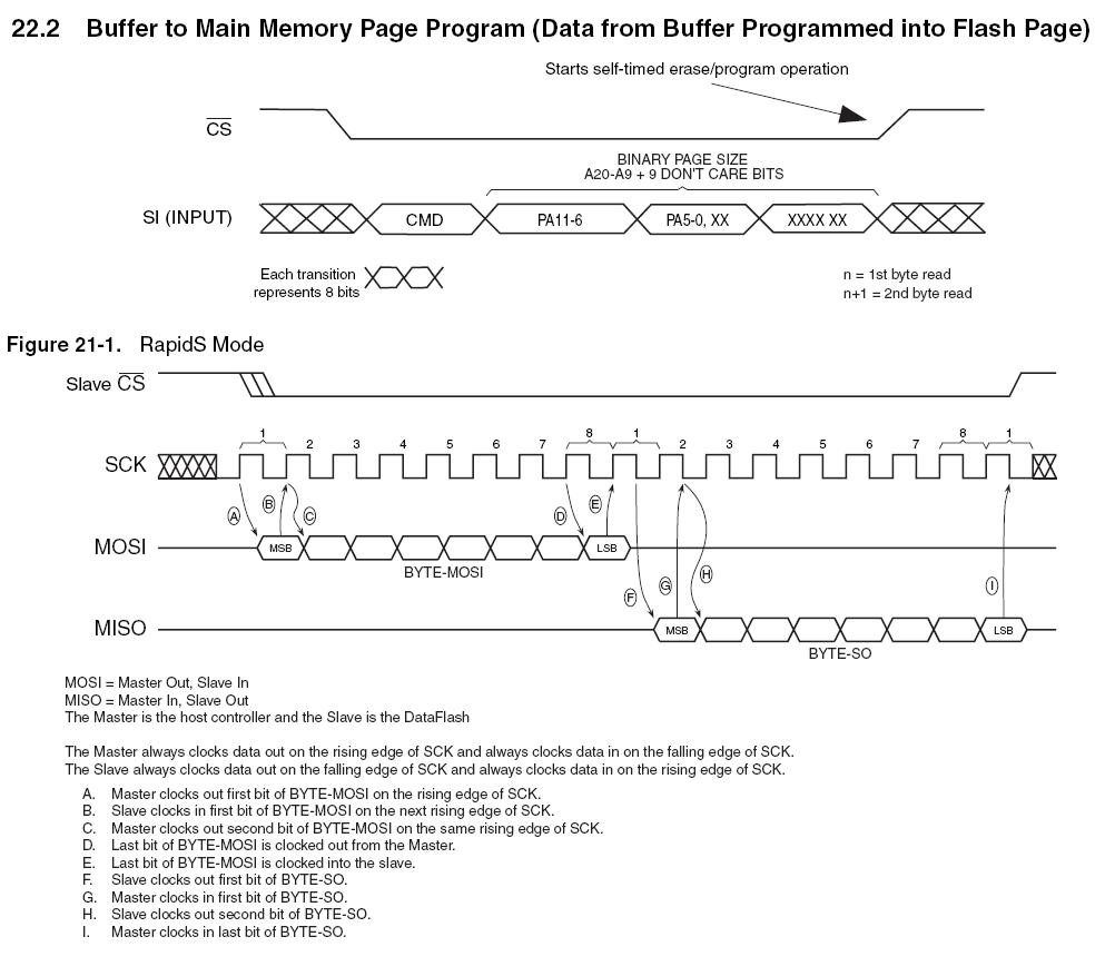
In the bottom set of waveforms in the attached file, it looks like the CS line can be driven low at the earliest during clk cycle 1, and at the latest before clock cycle 2.
However, if it is driven low at the start of clk cycle 1, this is before the first data bit is written, whereas if CS is driven low halfway through clk cycle 1, the first data bit will be ready.
This is the bit which is confusing me, do I drive CS low prior to doing the clk and data bits, or after the clock starts but before the data?
Any clarification (or experiences with the same IC) is appreciated [noparse]:)[/noparse]
Thanks,
Alec
▔▔▔▔▔▔▔▔▔▔▔▔▔▔▔▔▔▔▔▔▔▔▔▔
-Alec
My our page


Comments
!CS normally means Chip Select on Low, as this is a bus system. But - normally" - if you have only one device connected, you can leave it low at the device without any line at all.
Not with RapidS mode!
As the rising clock is used for reading the bus (by the slave) as well as changing it to the next value, it must be avoided that this first rise (when the master sets the very first bit) is "seen" by the slave. So:
Master action:
(a) Wait rising clock
(b) set DO and !CS
The single rule is: when you rise the clock your signal must be stable on the MOSI!
(There can be other rules, as there is no such thing as THE SPI protocoll but about 4 to 5...)
Ok so bringing CS low comes before everything [noparse]:)[/noparse] Thanks, thats the bit I was unsure about.
Heres how I understand it (This is running at 64Mhz if I got my timing right :P)
  Data <<= (32 - bits)

  delay := cnt

  outa[noparse][[/noparse]DF_SCK]~ 'SCK low
  waitcnt(delay += (clkfreq / 32_000_000))
  outa[noparse][[/noparse]DF_CS] ~ 'CS low

  repeat bits
    ' set the data line while the SCK high
    outa[noparse][[/noparse]DF_SCK]~~
    outa[noparse][[/noparse]DF_DATA] := (Data <-= 1) & 1
    waitcnt(delay += (clkfreq / 32_000_000))
    outa[noparse][[/noparse]DF_SCK] ~
    waitcnt(delay += (clkfreq / 32_000_000))
▔▔▔▔▔▔▔▔▔▔▔▔▔▔▔▔▔▔▔▔▔▔▔▔
-Alec
My our page
Please do it in the "normal" way: Just set your data on the bus and rise the clock..
(b) A SPIN instruction takes 5 to 10 us, so your WAITCNTs will work in a strange way
(c) Because you use SPIN your bandwidth will be about 50 k bits/s - don't cry
Use assembler instead!
Please do it in the "normal" way: Just set your data on the bus and rise the clock..***
OK [noparse]:D[/noparse] Will work through it tonight [noparse]:)[/noparse]
***(b) A SPIN instruction takes 5 to 10 us, so your WAITCNTs will work in a strange way
Oh, thanks for the heads up!
***(c) Because you use SPIN your bandwidth will be about 50 k bits/s - don't cry
Use assembler instead!
Ive never used Asm :P All I need is a simple routine to write data, x number of bits in length.
▔▔▔▔▔▔▔▔▔▔▔▔▔▔▔▔▔▔▔▔▔▔▔▔
-Alec
My our page
If you should need this - counter my intuition - then you should make a "two version loop":
 IF DelayCount
    repeat bits
      outa[noparse][[/noparse]DF_DATA] := (Data <-= 1) & 1
      outa[noparse][[/noparse]DF_SCK]~~
      repeat DelayCount
      outa[noparse][[/noparse]DF_SCK] ~
      repeat DelayCount
 ELSE
    repeat bits
      outa[noparse][[/noparse]DF_SCK] ~
      outa[noparse][[/noparse]DF_DATA] := (Data <-= 1) & 1
      outa[noparse][[/noparse]DF_SCK]~~
    outa[noparse][[/noparse]DF_SCK] ~
Post Edited (deSilva) : 9/25/2007 8:57:44 PM GMT
Thanks for that [noparse]:)[/noparse] I made it more complicated than it really is by the looks of things!
▔▔▔▔▔▔▔▔▔▔▔▔▔▔▔▔▔▔▔▔▔▔▔▔
-Alec
My our page