Shop OBEX P1 Docs P2 Docs Learn Events
Basic Stamp using DC Motors — Parallax Forums

Basic Stamp using DC Motors

dw101sdw101s Posts: 27
edited 2007-10-01 18:29 in BASIC Stamp
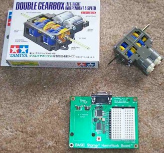
I am currently starting a project where I want to control two independant DC motors (Tamiya Double Gearbox, Left/Right·4 Speed Independant)·with my Basic Stamp Homework Board.· The Homework board uses a 9V battery which is plenty for these simple DC motors but I wanted to hook up the motors to the I/O ports but when I did this the voltage from the I/O ports went from around 5V to 0.· I have read in the Whats A Microcontroler book that the I/O ports have current limits so I was thinking about using a transistor but I couldnt get this to work out.· Does anyone have a schematic or suggestion on how to hook up this DC motor set to the basic stamp?· Thanks for any help.
329 x 307 - 46K

Comments

  • Mike GreenMike Green Posts: 23,101
    edited 2007-09-22 20:39
    Chapter 5 of the Process Control tutorial has some examples of using transistors to switch a motor or solenoid or relay on and off (here: www.parallax.com/detail.asp?product_id=28176).

    A 9V battery really is not adequate for running a motor. It may seem to work for a little while, but it'll run down quickly as you've seen. The I/O ports are not capable of driving a motor. They're designed for a maximum of about 20-30ma which is suitable for driving an LED. As you'll see in the tutorial, the motor can run off a different supply than the Stamp itself. I would suggest a 4-cell battery pack with 4 AA batteries. You can even use NiMH rechargables to save money. You can't run the Stamp off 4 NiMH batteries (they only put out 4.8V max.) You'll need to use 5 NiMH cells if you want to run the Stamp off the same supply as the motors (to get 6V).

    Post Edited (Mike Green) : 9/22/2007 8:45:25 PM GMT
  • UnsoundcodeUnsoundcode Posts: 1,532
    edited 2007-09-22 20:53
    I downloaded the attached doc from the Parallax forum quite a while ago. I find it simple to understand and I keep it on my desktop for reference.

    Jeff T
  • Mike GreenMike Green Posts: 23,101
    edited 2007-09-22 21:05
    It's not necessary to use two diodes. The diode across the motor will be enough because it dissipates the energy in the magnetic field before the reverse voltage can rise enough to cause trouble. It looks like a great guide otherwise.
  • Sutton MurraySutton Murray Posts: 88
    edited 2007-09-22 22:00
    Here is a link for building and controlled your motors 'http://www.bobblick.com/techref/projects/hbridge/hbridge.html'. You later would want to forward and reverse the motors, using your stamp. You will be needing an h-bridge similar to that find in the link.
  • D FaustD Faust Posts: 608
    edited 2007-09-22 22:03
    http://forums.parallax.com/showthread.php?p=643103

    ▔▔▔▔▔▔▔▔▔▔▔▔▔▔▔▔▔▔▔▔▔▔▔▔
    LOOKDOWN ThisThread, [noparse][[/noparse]Your_?, My_?, Cool_Thing], looknum
    LOOKUP looknum, [noparse][[/noparse]1, 2, 3], subnum
    ON subnum GOTO Hope_this_helps, Thanks!, WOW!!
    END 
    
  • dw101sdw101s Posts: 27
    edited 2007-09-25 01:36
    Thanks for the info. I was thinking about substituting an LED for the diode because and LED is a diode right? I am hoping that would work the same too.
  • D FaustD Faust Posts: 608
    edited 2007-09-25 02:00
    yeah, an led is a diode, but I am not sure if you·could use it / how to wire it up.

    ▔▔▔▔▔▔▔▔▔▔▔▔▔▔▔▔▔▔▔▔▔▔▔▔
    LOOKDOWN ThisThread, [noparse][[/noparse]Your_?, My_?, Cool_Thing], looknum
    LOOKUP looknum, [noparse][[/noparse]1, 2, 3], subnum
    ON subnum GOTO Hope_this_helps, Thanks!, WOW!!
    END 
    
  • Mike GreenMike Green Posts: 23,101
    edited 2007-09-25 03:22
    Theoretically you could use an LED, but the reverse voltage threshold for an LED isn't very good. Most LEDs, for example, are rated for only 5V reverse voltage. You could put a silicon diode (like a 1N4001) in series with the LED (to protect it) and you might see flashes when the field collapses.
  • pwillardpwillard Posts: 321
    edited 2007-09-25 13:41
    Sutton is right.· You will want bidirectional control on those motors so you will want an H-Bridge for Each Motor.· This will mean that you will need 8 discrete power transistors if you build it from scratch and the price of Bob Blick's start to add up.
    There is an H-Bridge chip designed to operate 2 motors called the L293.· Documented many places... try the link below

    http://www.me.umn.edu/courses/me2011/robot/technotes/L293/L293.html

    ▔▔▔▔▔▔▔▔▔▔▔▔▔▔▔▔▔▔▔▔▔▔▔▔

    There's nothing like a new idea and a warm soldering iron.
  • Jim ForkinJim Forkin Posts: 5
    edited 2007-09-25 15:33
    There is hardware and software details posted at this website for controlling dc motors.
    http://www.geocities.com/jimforkin2003/
  • dw101sdw101s Posts: 27
    edited 2007-09-30 23:17
    Trying to create an Hbridge and I have two NPN and two PNP transistors.· I have seen a ton of schematics and most of them use 8 transistors per motor to make it go forwards and backwards.· The second set of 4 transistors seem to be the small signal type like a 3904.· My question is can you make an Hbridge with just 4 transistors?
  • D FaustD Faust Posts: 608
    edited 2007-09-30 23:27
    http://forums.parallax.com/forums/default.aspx?f=10&m=62953 Look at the schematics by Beau.

    ▔▔▔▔▔▔▔▔▔▔▔▔▔▔▔▔▔▔▔▔▔▔▔▔
    LOOKDOWN ThisThread, [noparse][[/noparse]Your_?, My_?, Cool_Thing], looknum
    LOOKUP looknum, [noparse][[/noparse]1, 2, 3], subnum
    ON subnum GOTO Hope_this_helps, Thanks!, WOW!!
    END 
    
  • dw101sdw101s Posts: 27
    edited 2007-10-01 02:18
    Thanks for the reference.· However, I am kind of at a loss confused.gif right now as to what is not working correctly.· So I am posting my schematic of what I am doing to you all to see if I can get any expert advice on what the issue might be.

    I dont think I am connection this Hbridge up to the Basic Stamp Homework Board correctly·nor do I think I am incorporating the correct way to hook up the serparate battery pack with the stamp and bridge.

    I am only trying to get one direction to work right now so all I did was hook up to one I/O port on the Basic stamp.· All I did in the program was do a High 8 (open P8 I/O port) for 3 seconds and then I did a Low 8 (close P8 I/O port).
    1025 x 763 - 59K
  • Mike GreenMike Green Posts: 23,101
    edited 2007-10-01 02:30
    You need to connect those two points to two different (opposite) I/O pins. The base of the PNP transistor has to be grounded to turn it on. The base of the NPN transistor has to be connected to a high voltage (like logic high ... roughly 4.5V) to turn it on. When you connect the two bases to the same I/O pin, one of the transistors is always off, no matter what the I/O pin logic state.
  • Phil Pilgrim (PhiPi)Phil Pilgrim (PhiPi) Posts: 23,514
    edited 2007-10-01 04:03
    Don't forget to add current limiting resistors in series with the base connections. Otherwise you could damage either the transistors or your BASIC Stamp.

    -Phil
  • D FaustD Faust Posts: 608
    edited 2007-10-01 18:29
    Don't forget the backEMF protection diodes.

    ▔▔▔▔▔▔▔▔▔▔▔▔▔▔▔▔▔▔▔▔▔▔▔▔
    LOOKDOWN ThisThread, [noparse][[/noparse]Your_?, My_?, Cool_Thing], looknum
    LOOKUP looknum, [noparse][[/noparse]1, 2, 3], subnum
    ON subnum GOTO Hope_this_helps, Thanks!, WOW!!
    END 
    
Sign In or Register to comment.