Penguin New Servo Feet Video
Ok I gave up on finding my video camera and shot a short video with my PDA phone. It's not too bad for a phone vid. A little jumpy.
I haven't had time to work on the walk code for the new feet much this week, I still need to smooth out the transitions.
http://www.youtube.com/watch?v=5hA6oQE5Z9E
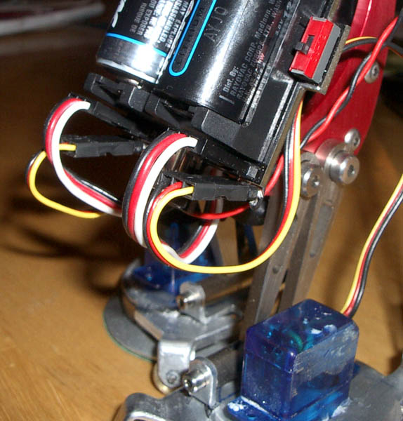
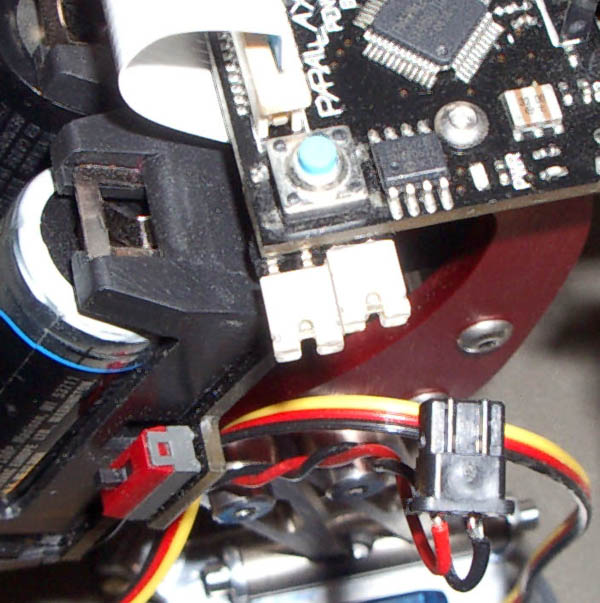
Here is a picture of where I put the port for the new servos.

By putting two jumpers in, the LED display becomes fully functional again.

The servo connectors are next to the tilt and stride servo conectors because there is not enough power on the computer board to power the servos.

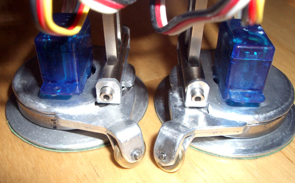
Here is a picture of just the feet.

Post Edited (Interact) : 9/22/2007 5:22:57 PM GMT
I haven't had time to work on the walk code for the new feet much this week, I still need to smooth out the transitions.
http://www.youtube.com/watch?v=5hA6oQE5Z9E
Here is a picture of where I put the port for the new servos.
By putting two jumpers in, the LED display becomes fully functional again.
The servo connectors are next to the tilt and stride servo conectors because there is not enough power on the computer board to power the servos.
Here is a picture of just the feet.
Post Edited (Interact) : 9/22/2007 5:22:57 PM GMT


Comments
The photos are very good - I like the neatness of the motherboard
mod. Well done!
I think we have a new kind of robot with these feet
making Penguin a four servo robot. It looks much more easy
to turn in various directions and much quicker.
You now hold the record for the very first hardware
modification to Penguin! I also like the software results
in the demo movie.
Where do you buy the feet?
humanoido
Now you have me thinking of doing this to my humanoid MANOI...
Darn. Too many cool things, too little time.
How can I buy the parts?
▔▔▔▔▔▔▔▔▔▔▔▔▔▔▔▔▔▔▔▔▔▔▔▔
slashsplat
/* Ira Chandler */
BotConnect.com
Still trying to figure out the pieces of the feet. Perhaps you could help with some more descriptions of what you used.
Carl
I will try to put up a drawing later today, once my store settles down.
How did you attach the servo? Tap tiny screw holes in
the metal for the horn?
humanoido
Here is a drawing (under statement) of the pieces.
The servo arm is connected to the cupped foot.
The cupped foot is·attached to the inside of the bearing.
The top piece is·attached to the outside of the bearing.
The servo body is·attached to the top piece.
Super nice job and very creative work. Congrats! ...Tiger
The "drawing program" is well .. I use quite a few in combination. this used Maya, and a hybrid render that I wrote part of. Texture's are from who knows where, when you do this stuff a lot you build up a huge texture library and I never remember where they originally come from. I do TV commercials that need CG, on the side.
Last night I played around with using a thrust bearing for the round foot to pivot on. It might work out but I need access to my mill and lathe which is in Orlando. Right now I am working in Washington, D.C.
Carl
▔▔▔▔▔▔▔▔▔▔▔▔▔▔▔▔▔▔▔▔▔▔▔▔
slashsplat
/* Ira Chandler */
BotConnect.com
Post Edited (slashsplat) : 9/26/2007 12:18:09 AM GMT
the part about your life stories. Now we know where
all of this incredible talent came from!
I remember the Interact microcomputer from 1979.
Like most new micros of that day, it had the cassette
tape standard built in, ran off an 8080 chip with base
8K and 2k ROM. It's reported that several thousand
machines were manufactured. BASIC was loaded in
from tape, and it ran off a TV - the video modular was
built inside. It had a very attractive all-in-one design
molded with the full ascii keyboard. It sold for
around $300. It was one of the great microcomputers
that significantly contributed to the overall evolution
of the computer as we know it today.
These computers are now in museums. If you own
an Interact computer, it's worth more than a hens'
golden egg.
humanoido