stupid photoresistor question
I know this is dumb and very elementary but..
Is there a simple way to set a pin high with a photoresistor without resorting to adding a capacitor and using rctime?
I'm basically using a white led and the photoresistor to isolate an industrial 17vdc sensor.
It works using the aforementioned rctime and just checking if time < 50, but it's a slow response and seems like it shouldn't be necessary.
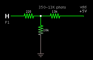
I attached the quick sketch of what I was trying (that obviously doesn't work).
The photoresistor value changes between 13Kohm to 350ohm when active. What's the simplest way to detect this?


Comments
▔▔▔▔▔▔▔▔▔▔▔▔▔▔▔▔▔▔▔▔▔▔▔▔
The aim is to have the junction of your voltage divider at logic level 0 in a dark condition ( between 1v and 1.2v should be good ) and as the light falls on the photoresistor the voltage at the junction of the divider will rise to logic level 1.
Divider voltage = R2/R1+R2 * V
Jeff T.
Do you have to see the white LED as well?
Use a photo transistor.
Photoresistors are inherently slow. A photo transistor is fast.
▔▔▔▔▔▔▔▔▔▔▔▔▔▔▔▔▔▔▔▔▔▔▔▔
"Everything in the world is purchased by labour; and our passions are the only causes of labor." -- David·Hume (1711-76)········
I just got it working 2 seconds ago and it seems to be working good, though the response isn't great. The response is probably being held down by the debug calls though. Just gotta tweak a little.
Thanks!
Works with TV remotes too.
▔▔▔▔▔▔▔▔▔▔▔▔▔▔▔▔▔▔▔▔▔▔▔▔
Have Fun
TR