

Inconsistent Current with Duty Cycle?
 Steel
Posts: 313
Steel
Posts: 313
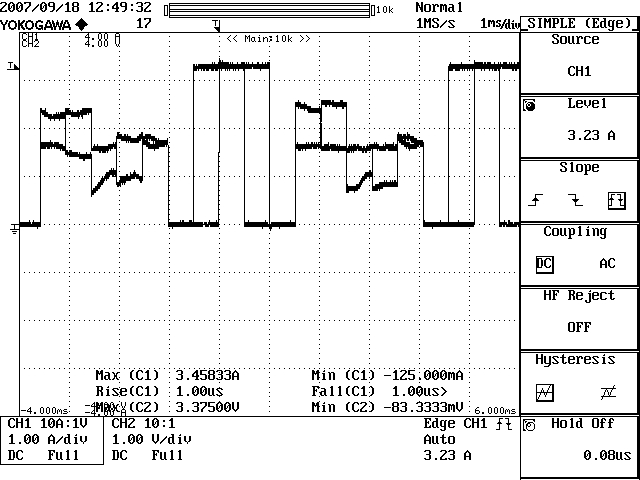
I have attached a scope capture of using the Counter "Duty" output.
On Rail levels $FFFF_FFFF and $0000_0000, the output current appears quite stable...however when a middle value is sent ($8000_0000, $C000_0000) the output current is quite inconsistent.
Is this a characteristic of the Propeller that needs to be filtered out?
The code is attached.· I have a 10k resistor attached to each output to get the voltage.
Shaun
640 x 480 - 168K

Comments
▔▔▔▔▔▔▔▔▔▔▔▔▔▔▔▔▔▔▔▔▔▔▔▔
Paul Baker
Propeller Applications Engineer
Parallax, Inc.
(b)
djnz Latch, Looplooks unhealthy. It has to be "#loop" in the first place.
▔▔▔▔▔▔▔▔▔▔▔▔▔▔▔▔▔▔▔▔▔▔▔▔
I actually just left the Amps label on the scope accidentally. I was using a current probe prior to this, and just forgot to switch it back. It wasn't reading 3.5A...but 3.5V. Sorry about that.
...And I don't have any averaging on the scope. It is taking 20MS/Second, and displaying those samples. I could do averaging...but I am not.
I am not running a low pass filter on the circuit. I am trying to monitor the 'true' output. I just have a 10k Resistor attached to the pin, and I am reading the voltage on the downstream side of the resistor. The Current across the resistor creates the true voltage and that is what I am monitoring right now.
There is no Cap, because even a .01uF cap on this signal does a great deal of rounding it out, and I would like to keep it as close to the 'real' propeller output as possible.
This 10k... Do you want to say you have connected it to ground?
Al right, this will do no harm...
And the fix of the #-bug has not changed the output?
On the other hand, why do you use an assembly program... there is no need for it and it makes the situation a little bit dubious..
Can you quickly recode it in SPIN and see what happens?
I think you're seeing sampling errors in your scope. The scope is just showing you what it saw over its 50nS sampling interval. The signal during this interval can have several transistions present, and what the scope samples will vary from interval to interval, depending on the ratio of highs to lows encountered. With an 80MHz clock rate coming from the Propeller, your scope would have to sample at 160Mhz to show you the "true" output. What you could do is slow the Propeller's clock to 10MHz. Then you'll be able to see the output.
-Phil
Post Edited (Phil Pilgrim (PhiPi)) : 9/18/2007 9:00:16 PM GMT
▔▔▔▔▔▔▔▔▔▔▔▔▔▔▔▔▔▔▔▔▔▔▔▔
Paul Baker
Propeller Applications Engineer
Parallax, Inc.
I studied the oscillogram now, and think it is exactly what has to be expected in this somewhat unclear RC situation. Any parasitic capacity (even a finger!) will influence the "integration" behaviour.
When adjusting to the oscilloscope's capability, clean 0/1 patterns should be seen...
▔▔▔▔▔▔▔▔▔▔▔▔▔▔▔▔▔▔▔▔▔▔▔▔
The RC low pass filter shown at the top of the program has a time constant of 1 millisecond. Even an RC filter with a microsecond time constant can give significant filtering of the 12.5nS time slots. Where is your 10k resistor? If it goes from the Prop pin to the input of the 'scope, then it would provide 300 nanosecond RC filtering with the ~30pf input capacitance of the 'scope (depending on the probe).
▔▔▔▔▔▔▔▔▔▔▔▔▔▔▔▔▔▔▔▔▔▔▔▔
Tracy Allen
www.emesystems.com
...Also, if it was a scope issue, then it would show the inconsistencies at the rails ($0000_0000 and $FFFF_FFFF). The only'wobbling' is on the Frequencies between $4000_0000 and C000_0000 (In this test setup)
The 10k resistor is connected directly to the output pin, and the other end is connected directly to the scope probe. There is no capacitor and no extra components. I am just reading the Voltage that directly represents the Current from the pin. There are no fingers
The scope gnd is attached to VSS.
I put it in assembly because I am going to have a lot more in this application that I wish to have in ASM. This is not the only thing that I am doing. Having this code in ASM instead of SPIN should not affect the actual pin characteristics
▔▔▔▔▔▔▔▔▔▔▔▔▔▔▔▔▔▔▔▔▔▔▔▔
Paul Baker
Propeller Applications Engineer
Parallax, Inc.
Maybe I am wrong, but I think your scope is triggering on both edges.
Did you try to set slope on raising (or faling) edge?
A modern scope is not something you just throw at a signal and then come crying saying your signal is wrong. It needs some practicing, studying and understanding.
Like a gun. It is easy to hurt oneself if one hasn't understood and practiced.
▔▔▔▔▔▔▔▔▔▔▔▔▔▔▔▔▔▔▔▔▔▔▔▔
Are you really aware that the "duty"-output is a tiny 12,5 ns spike? There in fact is no need to look at it "as such" (Why?). The tricky things will be to make sure it does what it shall do in the context of your circuit (triggering something, being integrated,....).
Do you understand the concept (and the involved parameters) how a capacitor is used as "low pass filter" or an "integrator"?
Or, slow down the Propeller clock to 5 megahertz (leave out the PLL16x), and the logic is all the same, but the output time slots 200 nanoseconds instead of 12.5, easier to capture.
▔▔▔▔▔▔▔▔▔▔▔▔▔▔▔▔▔▔▔▔▔▔▔▔
Tracy Allen
www.emesystems.com
Steel, You need some capacitance after the 10K resistor. 100nF is too much. Your pulse width looks like its around 500uS so an RC time constant of 10uS should give you plenty of filtering. With a 10K resistor that gives a capacitance of 1nF.
Tom
ps More later, I must leave for work. damn!
BTW Steel, when the output is max or min it is not switching which is why it looks clean no matter what setting you have your dso on. If I may be cheeky, at least with a car you need a license before you can take it out on the road [noparse]:)[/noparse]
*Peter*
damn! I better do some work!
Second, it sets the output "high" whenever PHSx overflows by adding FRQx each system (!) clock. This is a tiny spike of e.g. 12.5 ns, except when the next addition leads to another overflow...
This is simplicity itself and hardly to misunderstand.
However the consequences might not always be clear....
(1) This it NOT a PWM!
(2) 12.5 ns is not much!
(3) There is generally no strict regularity (!) in the pulses, except FRQx is a power of 2.
(4) for the latter reason, the PLL should ALWAYS be used after the timer
Example: When FRQx is around $F......... PHSx will overflow many times (e.g. 16x) before a tiny zero break will bring the timer back to 16 highs, but sometimes 15 only. This is the trade-off for a very simple and transparent implementation.
Edit: Tried to make it even clearer...
Post Edited (deSilva) : 9/19/2007 3:08:58 PM GMT
Peter, My knowledge of the propeller counters is very limited at this time and I have a problem understanding how an I/O·pin can switch at the full 80MHz rate.· Is this really possible?
Tom
damn! I better do some work now that I'm at work.
You better believe it, and it doesn't stop at 80MHz either, more like 128MHz. Have you ever tried the Synth object?
*Peter*
damn! I can't remember what work I was going to do.
Peter, My next project must use a counter so I suppose I'll be an "Xpurt" by the time I'm done.
Tom
damn! I can't remember what you were supposed to be doing either.
I was really just trying to verify that there counter outputs were consistent. It could have been a fairly easy yes/no answer.
The reason why I went into the equipment that I am using is because instead of the yes/no answer, it became a question of my test setup. As far as 'overlapping' signals, those are 2 different signals (as you would see in the code) that I was using for testing.
I don't feel that there is any reason to 'defend' my credentials, background, or equipment knowledge when all of that is a complete sidetrack to the original question.
I am really trying to understand the current/voltage spikes at a low level, and that is it. I just needed to know "Yes, unfortunately because of the way the counters work, there will be 12.5nS changes" or a "No. We tested the current output of the propeller to be stable within a 5% tolerance"
This answer quite suffices: "There is generally no strict regularity (!) in the pulses, except FRQx is a power of 2". -Thank you DeSilva.
If I wanted to be referred to as 'crying'...then I would not have come to a forum for engineers.
Sorry. I just feel that some of the responses were fairly out of line. Thank you to those who helped.
I understand that you refer to my posts, mostly.
We have had some "hopeless" cases lately. So I, for one, was prepared to see yet another round of these endless Q&A sessions, which sometimes gets on your nerves.
I can not judge you from your possibly/probably charming and competent personality. All I have to go after is what you write. And what you wrote did not impress me a bit. You have clearly indicated in the headline that it is about current and not voltage and you are also discussinmg current until corrected. Anyone in this business knows that more than a 20 or 30 mA is next to impossible out of a micro pin. And that 3 A will fry the circuit immediatly. That alone makes me very suspicious.
You also have no clue that you are sampling with a 1 microsecond interval - but say that you have a 2 GS/s (500 ps) going. Another mistake that you would not expect from a person as competent as you say you are. Plus a few other things that I think needed to be mentioned to put you on track.
I am rather tired of the "Hey! This doesn't work!" threads. Especially those where the reason is lack of understanding of basic measurement techniques. They cause a lot of unnecessary confusion.
I understand that you don't like my attitude. I am rather used to that. But I think that a certain degree of technical correctness and fairness should be kept in this thread. I happened to be the bad guy this time. But there are several of us. And I am glad for that.
▔▔▔▔▔▔▔▔▔▔▔▔▔▔▔▔▔▔▔▔▔▔▔▔
Tom
In light of that, it does not make sense to me that you say, <This answer quite suffices: "There is generally no strict regularity (!) in the pulses, except FRQx is a power of 2". -Thank you DeSilva.> I think deSilva is quite right about that answer, but it doesn't really have much to do with the original question you posed. Also it would be wrong to say that the pulses are either regular or irregular, without a context of what you are trying to accomplish.
Here is an excerpt from your statement in the first message..."
>>" ... when a middle value is sent ($8000_0000, $C000_0000) the output current is quite inconsistent.
>>Is this a characteristic of the Propeller that needs to be filtered out?
>>The code is attached. I have a 10k resistor attached to each output to get the voltage.
How can we give a yes or no answer to that regarding propeller timing issues, when the obvious issue is amplitude? The first red flag that goes up for me (as an engineer) is when I read "the output current is quite inconsistent" and "I have a 10k resistor ... to get the voltage". Maybe it is a question of language or maybe I am misunderstanding, but why, I immediately ask, does Steel need a 10k resistor to get the voltage? The output of the Prop is already a voltage, and the usual application of duty mode is to generate analog DC voltage. Similar reactions occur when I read your middle sentence below, concerning the 12.5nS "changes" and the "current output" being stable to within 5%. huh? We are quite willing to help here, but we can help best when we have a good target for answers.
▔▔▔▔▔▔▔▔▔▔▔▔▔▔▔▔▔▔▔▔▔▔▔▔
Tracy Allen
www.emesystems.com
Post Edited (Tracy Allen) : 9/19/2007 11:56:21 PM GMT
Sorry Steel, I think this is one of those days for you so why wouldn't you get a ribbing, we are engineers who know how to look at the lighter side of our own stuff-ups (and others). The fact that we are taking the time to figure out what you are saying and to try to be helpful would indicate that on some scale we are your friends. Examine the facts and what you yourself have said, how else can we answer?
So please don't feel offended by our comments as they are not meant to hurt (too much
Have a good day.
*Peter*