

ANALOGIN circuit used in vehicle
 VonSzarvas
Posts: 3,634
VonSzarvas
Posts: 3,634
Hello all,
Please may I ask for some guidance?
I have a happy ANALOGIN / POT circuit running, based on the various code and circuit samples given with the SX.
In the real world, I would like to put the circuit in a vehicle, to monitor the level of water in a tank (so the fish don't suffer - its a fish lorry! - too much detail perhaps..).
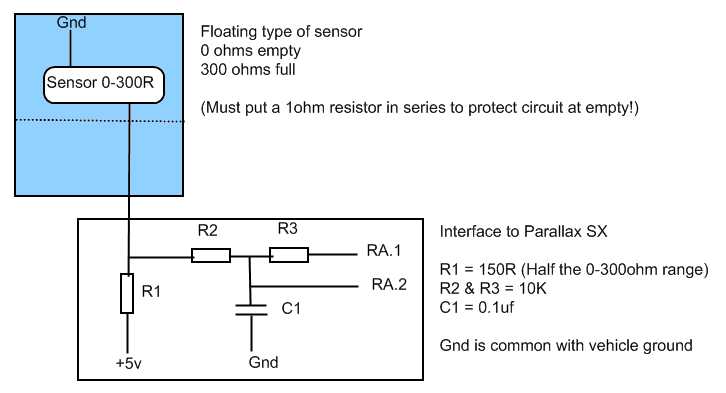
Detail: The level sensor is effectively a simple variable resistor, 0 to 300 ohms. One side connects to vehicle body / gnd. The other side is where I would need to connect my circuit, via a 3-4m cable from the tank to the vehicle cab.
My dev board connects to the vehicle 12v battery via an L7805, giving a really stable 5v up to approx. 400ma.
So Ideally I would like to use the regulated 5v as a good reference, and send that down the single wire to the sender. Thus I would need to read the voltage depending on the position of the floating sensor/rheostat.
So the difficulty I have is this: The circuit example given shows the 0.1uf capacitor connected to ground, and the positive voltage coming in to be ANALOGIN'd.
But for install in a vehicle, this should be reversed I think ? As the sensor is grounded on its other side. I cannot change that as its casing is actually grounded.
Does that make sense? I made a small drawing here......
I tried adding a type of voltage divider to the front of the sample circuit, but I get about 3 values in the 255 range. Maybe I just need some advice on selecting the right components, maybe the circuit is just all wrong!
Any advice would great!
Thank you all.
Please may I ask for some guidance?
I have a happy ANALOGIN / POT circuit running, based on the various code and circuit samples given with the SX.
In the real world, I would like to put the circuit in a vehicle, to monitor the level of water in a tank (so the fish don't suffer - its a fish lorry! - too much detail perhaps..).
Detail: The level sensor is effectively a simple variable resistor, 0 to 300 ohms. One side connects to vehicle body / gnd. The other side is where I would need to connect my circuit, via a 3-4m cable from the tank to the vehicle cab.
My dev board connects to the vehicle 12v battery via an L7805, giving a really stable 5v up to approx. 400ma.
So Ideally I would like to use the regulated 5v as a good reference, and send that down the single wire to the sender. Thus I would need to read the voltage depending on the position of the floating sensor/rheostat.
So the difficulty I have is this: The circuit example given shows the 0.1uf capacitor connected to ground, and the positive voltage coming in to be ANALOGIN'd.
But for install in a vehicle, this should be reversed I think ? As the sensor is grounded on its other side. I cannot change that as its casing is actually grounded.
Does that make sense? I made a small drawing here......
I tried adding a type of voltage divider to the front of the sample circuit, but I get about 3 values in the 255 range. Maybe I just need some advice on selecting the right components, maybe the circuit is just all wrong!
Any advice would great!
Thank you all.
726 x 393 - 23K
Comments
· Your circuit looks reasonable. Only the maximum voltage you get will be about 3.33 volts (when the sensor is at 300 ohms). And when the sensor is at 0 ohms you will have 33mA going through the 150 ohm resistor.
· I would suggest you use a 250 ohm resistor to +5V and set the ANALOGIN input pin to TTL level (instead of CMOS level). Using TTL levels gives 255 when the voltage is 2.8volts. This should give you more resolution, and only draw 20mA when the sensor is at zero volts.
Bean.
▔▔▔▔▔▔▔▔▔▔▔▔▔▔▔▔▔▔▔▔▔▔▔▔
I know what I know, don't confuse me with the facts...
- - - - - - - - - - - - - - - - - - - - - - - - - - - - - - -
www.hittconsulting.com
·