12bitADC trace scope up to 83 kHz
Hi,
I was really fascinated by this 20 MHz digital scope project and a bit· disappointed it can't be made to work on a USB-serial plug. I wanted to debug my problems with serial port at 9600 baud so decided to build· an analog trace scope. As you see on photos it works!
It uses serial 12bit-ADC (MAX144) which can be readout at 83 kHz using one cog under ASM. The version· I got· to work features· a circular buffer· w/ 220 bins.· User can set:
- sampling period:· any up to 83kHz
- trigger threshold in ADC units
- select to trigger on leading or trailing edge of the signal
- pick # of pre-trigger bins to be·preserved (in expense of 220 bins total available)
- reset of a·HUB variable from the main program causes other cog running ASM code to activate trigger and take another set of 220 data points
The graphic part is very primitive, no user interface, one needs to hardcod # of X,Y pixels, # of divisions and set conversion between world coordinates and· screen pixels.
I have attached the main SPIN code for illustration how simple· is the interface.
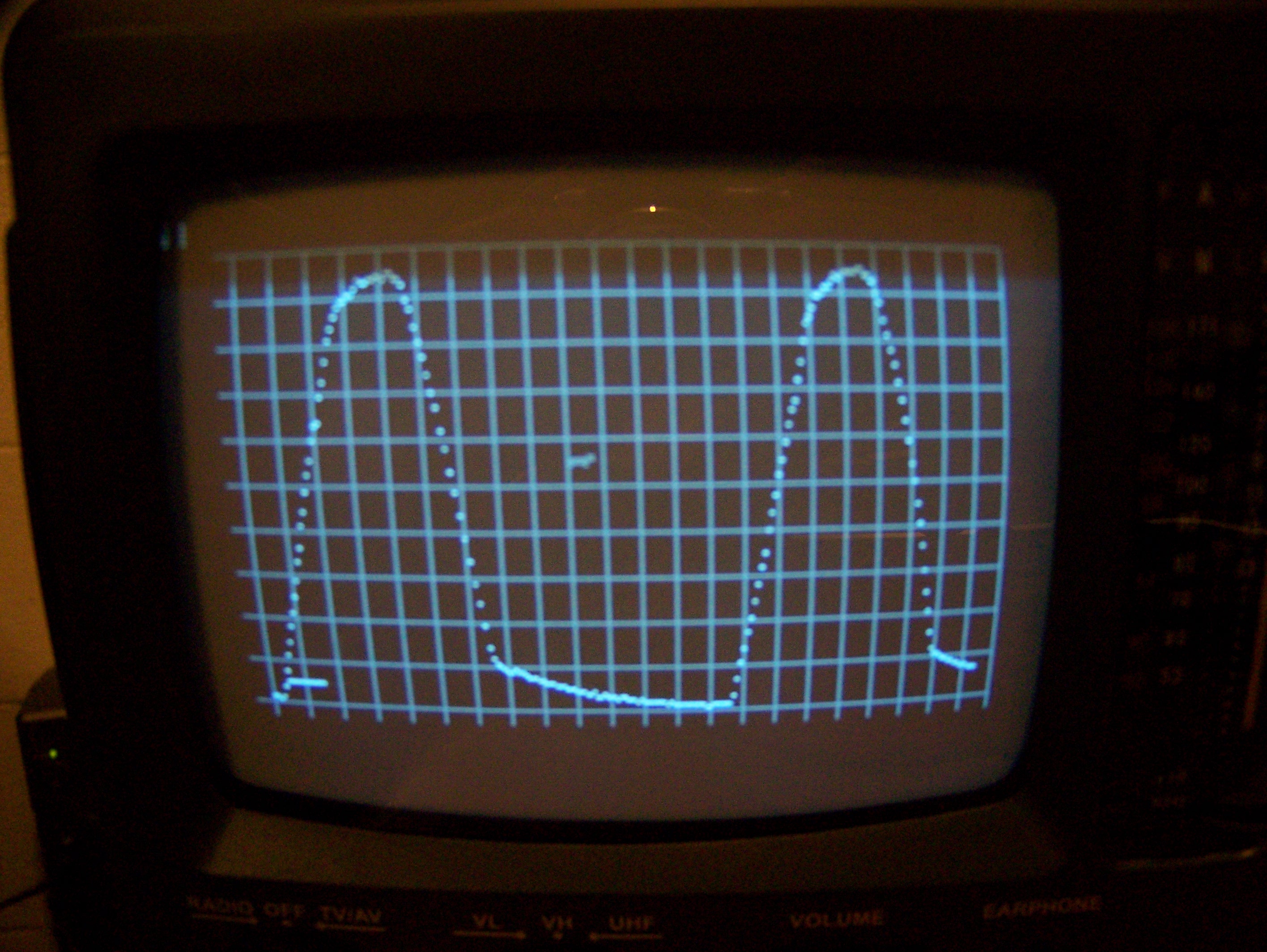
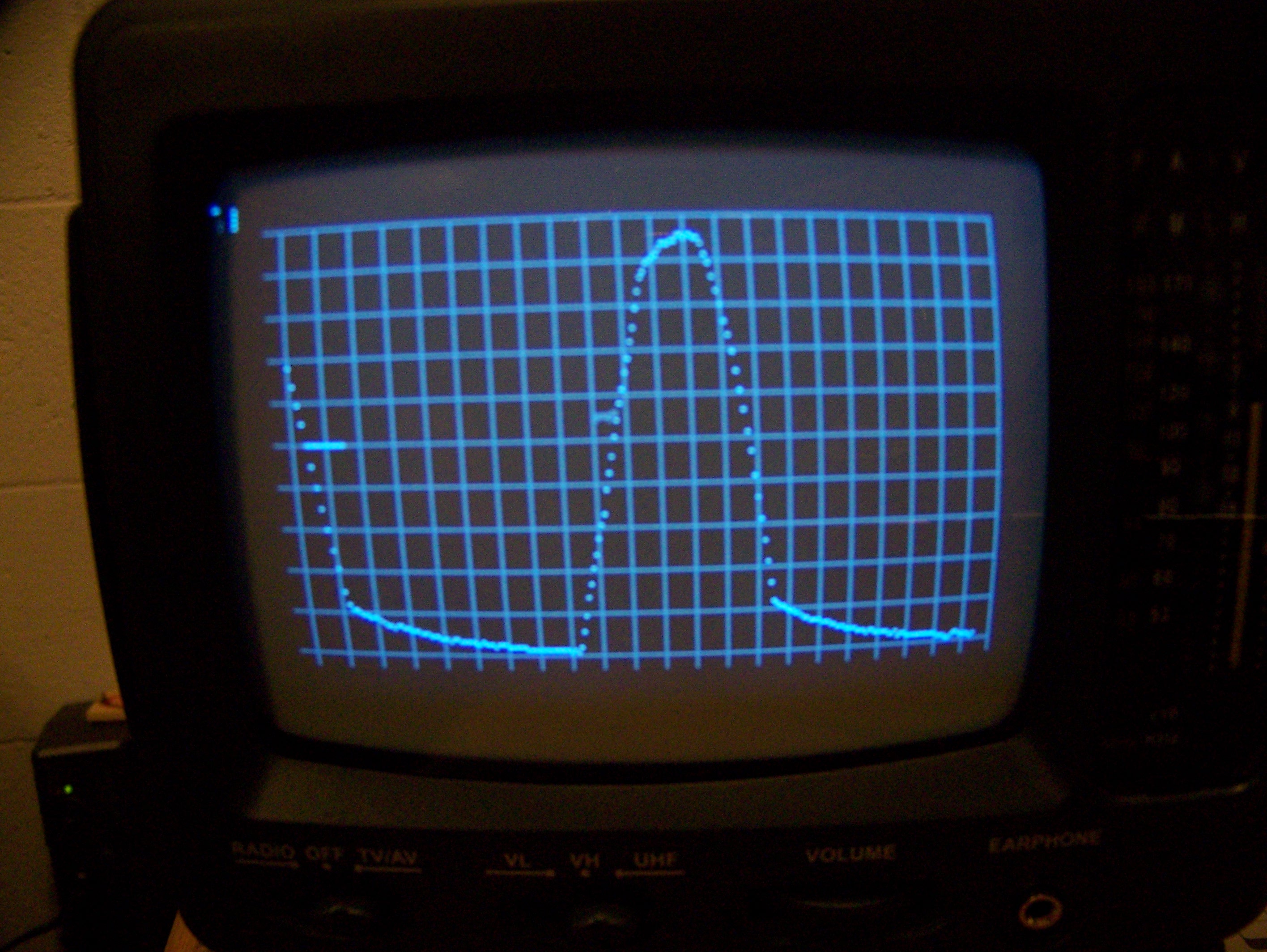
Attached photos show 60 Hz AC voltage· passed through a diode and clamped w/ small capacitor. The maxY on the display is set to 2000 ADC,· maxX=220 pixels.
Figs 1 & 2 were taken·w/ sampling rate of 8 kHz.
Fig 1 uses· trigger threshold of 100ADC·on positive edge (marked as short horizontal bar)
Fig 2 uses threshold of 1000 ADC·on negative edge.
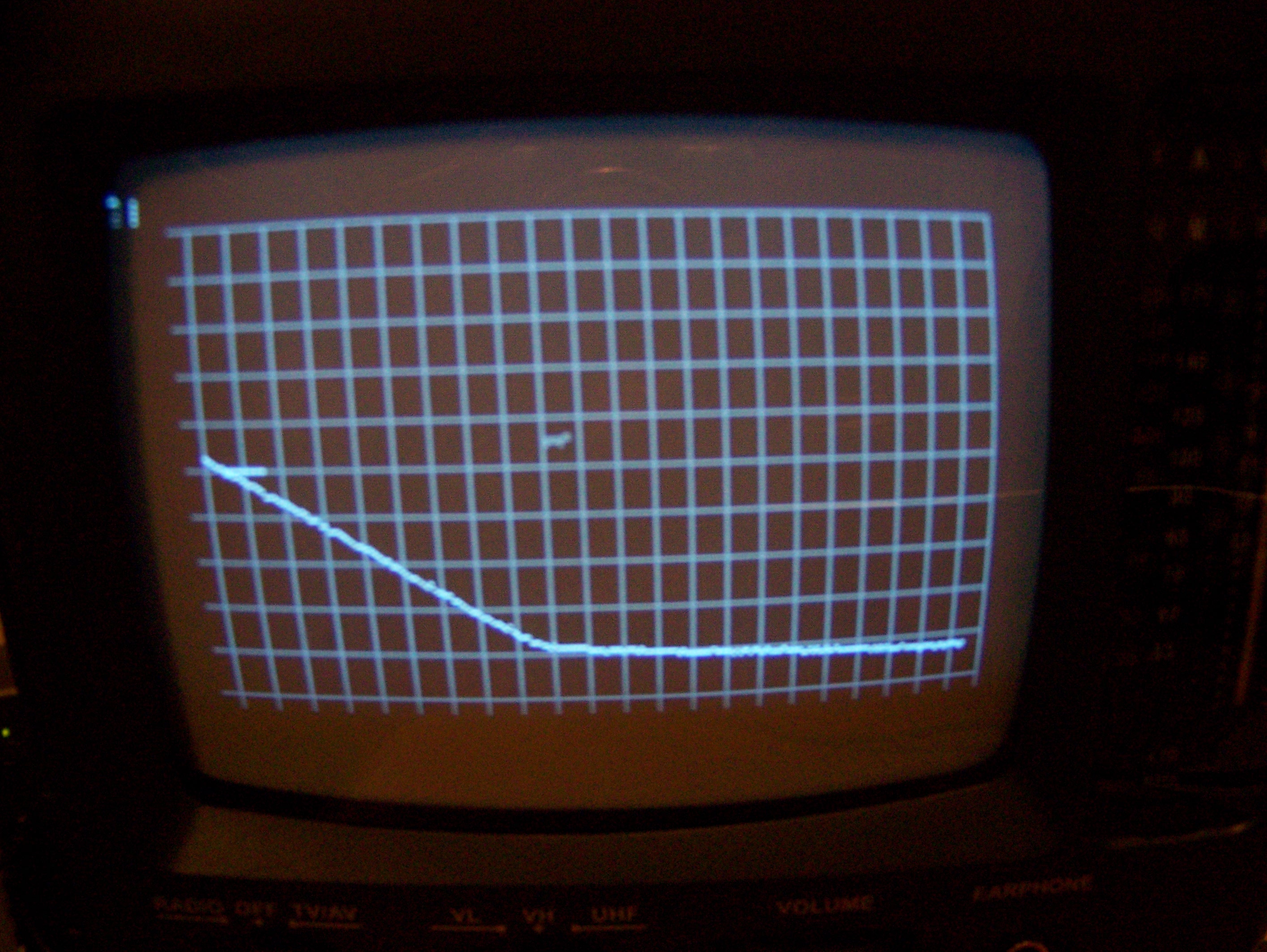
Fig 3 is as fig 2 except I used maximal possible sampling rate of 83 kHz.
It was a lot of fun working on this using Propeller cogs (after I was advised to not use local variables in assembler code - thanks deSilva !)
I'll be happy to share the code if anyone wants it. It is moderately commented.
Jan
September 15, 207 - full code is attached
Post Edited (janb) : 9/15/2007 5:43:19 PM GMT


Comments
this sound interesting! Congratulations.
I am working (slowly) on a dual channel, 8 bit "Propscope". And had great problems with the preamplifyers.
I would be interested, if you would post the code and the circuit.
Christof
it took me a while to cleanup the code. It is uploaded now to the first message.
There are 2 'main' SPIN programs.
*graphic scope looks cool, but has very little debug info. It is set up w/
a ring buffer of 215 , 8kHz sampling, trigger on the leading edge if
ADC exceeds 200,
store 5 pre-trigger samples
*'text'-scope prints on the screen ADC values. It has shorter buffer of
24 values so the screen does not scroll too much.
Both call the interface OBJ which initializes an array f values and
pointers which is finally passed to the ASM code.
Hardware setup is shown in both main codes. If you attach a LED to one
prop pin you will be able to monitor stat of the cog running the ASM
code. In particular if it dies the LED will stop flashing. I let the
code run for 36 hours in this 8kHz mode and it was still alive this morning.
Let me know if more details is needed or if anything can be improved.
Jan
well, not all goes smooth. I tried to use the graphic version of my scope to some real task.
Added just one line to the list of objects
VAR
·· long dataAr[noparse][[/noparse]arLen] '· I/O data array
OBJ
· scope :"ScopeDisplay+TV"
· adc·· :"Max144-trig1"
· rs :"Simple_Serial"· <== new object declaration
PUB main
.......
(full main-code is attached, it uses oher objects from .zip file from the top of this thread, no MAX144 hardware is needed to reproduce this problem)·
And TV screen displays garbage instead of nice grid of lines.
I was thinking as long as I do not any method of an OBJ it should only use up some memory but not affect execution of the working code. Obviously I'm wrong.
Perhaps anyone knows how to merge my code w/ serial IO OBJ?
Jan
thank you for the info. I will try to understand your assembler code.
This will take some time....
Best regards
Christof
Your program has now (have a look with F8):
1633 longs plus
458 longs variables
=2091 longs = 8 KB
Bingo!
Edit: Some days ago, Mark Bramwell had the same problem:
http://forums.parallax.com/showthread.php?p=673946
Maybe some of the suggestions there will be helpful to you...
Post Edited (deSilva) : 9/17/2007 7:51:31 PM GMT
you have saved me again! I droped the·double buffer and it works now!
Below is a snap shot of· serial trannsmission of $11,$0 sent out by one of the probs pins at 9600 bouds and capture by the ADC+80kHz scope running on other cogs.
The·vertical grid was·matched to ADC sampling rate of ·83kHz so one may count individual bits.
The start bit is clearly seen, next it drops to 0 for one bit, goes high for 3 bits, etc.
Jan