

BS2 controlled roving lights circuit
 Morrolan
Posts: 98
Morrolan
Posts: 98
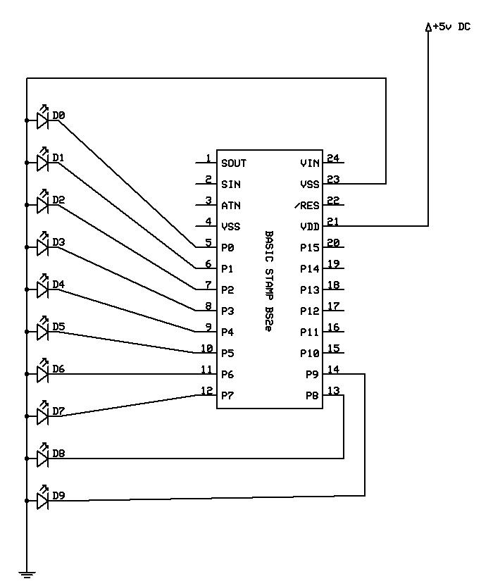
Hi guys, I need to make a circuit which "roves" up a scale of 10 LED's. I can do this easily with a stamp, as only 1 LED is ever lit at a time, but it consumes 10 I/O pins in doing so!
What I want to create is a circuit (probably going to involve an NE555 or two) which, when turned on by a single I/O pin (i.e. it receives 5V) I want it to rove through the LED's one at a time.
The code to do it with a stamp is simply:
etc, for each pin.
The thing is, I don't know how I can switch between each LED in turn without using a stamp?
Any help would be greatly appreciated.
Kind Regards,
Morrolan
edit: I've attached a simply circuit diagram of the stamp method, just in case.

Post Edited (Morrolan) : 9/12/2007 10:55:07 AM GMT
What I want to create is a circuit (probably going to involve an NE555 or two) which, when turned on by a single I/O pin (i.e. it receives 5V) I want it to rove through the LED's one at a time.
The code to do it with a stamp is simply:
LOW 0
PAUSE 100
HIGH 0
PAUSE 100
LOW 0

LOW 1
PAUSE 100
HIGH 1
PAUSE 100
LOW 1
etc, for each pin.
The thing is, I don't know how I can switch between each LED in turn without using a stamp?
Any help would be greatly appreciated.
Kind Regards,
Morrolan
edit: I've attached a simply circuit diagram of the stamp method, just in case.
Post Edited (Morrolan) : 9/12/2007 10:55:07 AM GMT
683 x 832 - 50K
Comments
A 4017 decade counter IC will do exactly what you're looking for. Do a Google search for 4017 circuits and you'll have what you want. The IC has ten outputs and you can use any or all of them... as the chip receives clock pulses, it steps through each of the outputs one at a time. Your circuit can either be stand alone, using a 555 timer to generate the clock pulses, or you can use a Basic Stamp for that purpose and have more control and fun... the choice is yours.
Tim
Edit: Here is a link for some·more information to help·get you started:
http://members.shaw.ca/roma/thirty-four.html
You can also use transistors or relays·on the 4017 outputs to drive larger loads if needed as shown in the 10 Channel LED Sequencer on this page:
http://ourworld.compuserve.com/homepages/Bill_Bowden/page5.htm
I should have mentioned that you can cascade these IC's too, if you·want more than 10 outputs.· 4017's are very versatile and fun!
Post Edited (Tim-M) : 9/12/2007 2:39:56 PM GMT
www.electronics-lab.com/projects/motor_light/028/
This looks perfect and cheap, (Maplin in the UK are cheap enough for most things, plus they have a new shop is around the corner so no postage costs).
I'm reading up on my electronics again, but whereabouts (and how) in that circuit would I incorporate a STAMP I/O pin?
Many Thanks,
Morrolan
▔▔▔▔▔▔▔▔▔▔▔▔▔▔▔▔▔▔▔▔▔▔▔▔
Flying is simple. You just throw yourself at the ground and miss.
Tim
The thing is though, this is saying that I want to use the stamp to control the logic and the steps, but the stamp will be busy doing other things mostly, and I don't want to tie up half of the stamps instruction cycles with a few status LED's.
What I'm more interested in, is somehow using the I/O pin on the stamp as a switch via a relay - i.e. at the beginning of the program when certain criteria are met, the stamp can simply "switch on" this pre-existing circuit and then forget about it until it is time to turn it off, giving me more processing instructions (and simpler code) to play with.
▔▔▔▔▔▔▔▔▔▔▔▔▔▔▔▔▔▔▔▔▔▔▔▔
Flying is simple. You just throw yourself at the ground and miss.
Tim
This is my first post to the forums. I'm new to both electronics in general and the BOE-BOT/BASIC STAMP.
I have been trying to do something like this myself. I've successful connected the LEDs to the 4017 and successfully run the trigger from both a SPDT switch (alternates between V+ and gnd) and a 555 timer.
My problems comes when I connect the trigger on the 4017 to the BASIC STAMP. No matter what programming I use I get the same result. The LEDs rapidly cycle thourth continously (just over 1 second to cycle sequenially through all 10 LEDs)
I have pin 14 on the 4017 connected to pin 10 on the BASIC STAMP, using the code below.
do
high 10
pause 5000
low 10
pause 5000
loop
I figure I've missed something so simple that anyone with experience wouldn't mention it. In previous posts to this thread connecting to 4017 to the BASIC STAMP has been mentioned, but is it really as straight forward as one wire between the 4017 and BASIC STAMP?
PS. I'm a newbie, forgive me if adding this to this pre existing thread was inappropraite. It was the closest I could find.