

led and switch on a single pin
 Chad George
Posts: 138
Chad George
Posts: 138
This may be a little off topic, but it's for a propeller based project so here goes.
I'm working on a design and I've used all but one pin (seems to happen alot), but I still
need both a switch input and a led output.
Now if the switch is allowed to affect the led (ie turn it on when pressed) then this isn't
even worth asking about, but the catch is that I want the led to be on ONLY if the I/O pin is
low. When its an input I want to be able to read the switch but not turn on/off the led
So like everything I googled the problem to death, but found nothing.
Then I fiddled around in Multisim until I got something that works.
I'm putting this out for comments and suggestions because I feel that it isn't as
efficient as it could be. It feels a bit like trying to kill a fly with a nuclear bomb.
I'm sure there's a simple and elegant solution but I haven't found it yet.
And just to clarify things, in my schematic there are two leds and two switches.
This is because I'm actually going to two propellers (each with only one pin left)
Thanks,
Chad
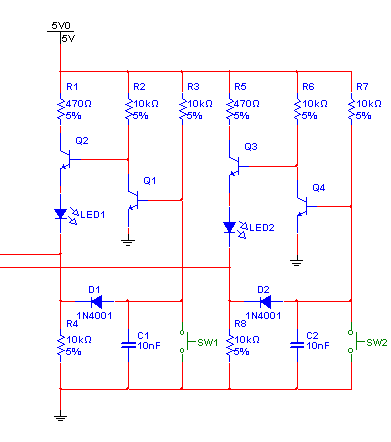
391 x 442 - 7K
Comments
Sounds like you'll short out the Prop's pin in a sense.
▔▔▔▔▔▔▔▔▔▔▔▔▔▔▔▔▔▔▔▔▔▔▔▔
Harley Shanko
-Phil
Like Phil said, I plan to periodically toggle the pin from an output to an input just long enough to read the input, but not long enough to be visible on the led.
Ziggy,
At first I thought the same thing and tried various ways to do that but couldn't quite get it so that the switch wouldn't force the LED on or off when it was pressed. But maybe I didn't implement it the way your suggesting. If you have time to throw a sketch together to clear up any ambiguity I'd be interested in building it to try.
Phil,
I tried your solution (I used a 2N6659 for the Mosfet) But it has the same problem that every other design I made has.
It drives the led "ON" when the switch is pressed. Basically I want the led to be completely independent of the switch so that it doesn't drive on and it doesn't hold it off. This is so I can do things like "press the switch until the led flashes 3 times"
I really struggled with this point. The pin has to drive the led with a high or low signal. If the switch's input uses the same level it will drive the led too. If its the opposite signal then it prevents the led from turning on.
Thanks again,
Chad
Post Edited (Chad George) : 9/12/2007 11:29:14 AM GMT
You'd have to account for this when trying to read the button state from the propeller, of course, so this might require a short polling loop instead of just a single ina.
This pulse train could come from some other component, maybe a timer IC. Or perhaps one of the pins of the propeller that you're already using as output to something else, could be (ab)used for this, if it happens to generate a signal that works.
▔▔▔▔▔▔▔▔▔▔▔▔▔▔▔▔▔▔▔▔▔▔▔▔
The more I know, the more I know I don't know.· Is this what they call Wisdom?
When the prop pin is an input, the potential divider outputs either 0.8V or 2.3V depending on Sw1. According to the prop data sheet, less than about 0.99V will read as logic low, and higher than about 2.1V will read as logic high. The prop should be able to read the state of the switch. The LED will not light since there is insufficient voltage across it (the voltage on the prop pin is still too high, even at 0.8V).
When the prop pin is set as an output, and the pin is driven low, then the LED will light, as there is now sufficient voltage across it. The 8K resistor is effectively bypassed, and the 25K resistor will be connected from 3.3v to ground. Pressing the switch just causes current to flow through the 4k resistor.
When the prop pin is set as an output, and the pin is driven high, then the LED will not light, as it is reverse biased. The 25K resistor is effectively bypassed, and the 8K resistor will be connected from 3.3v to ground. Pressing the switch just connects bothe ends of the 4K resistor to 3.3V.
To use with a program, you would leave the pin as an output most of the time, and only switch it to an input for long enough to read the switch (a matter of milliseconds at most). You could check the switch many times a second without difficulty.
If you really wanted to, you could probably do the same thing with a latch or flip-flop, not sensitive enough to read the switch but able to see and buffer outputs from the prop. Or just use an optocoupler in place of the LED.
▔▔▔▔▔▔▔▔▔▔▔▔▔▔▔▔▔▔▔▔▔▔▔▔
The more I know, the more I know I don't know.· Is this what they call Wisdom?
▔▔▔▔▔▔▔▔▔▔▔▔▔▔▔▔▔▔▔▔▔▔▔▔
The more I know, the more I know I don't know.· Is this what they call Wisdom?
@ Chad George : If you're working on the design, then why not have the LED on when Propeller pin is high ? That could be easier to solve.
My design won't turn the LED on when the switch is pressed if the port pin is an output and being held low. You have to keep the pin as an output all the time, except when the switch is being read. This doesn't mean you can't sample the switch often, just that you can't leave the input floating afterwards. Fortunately, the Propeller makes this pretty easy:
To read the switch:
DIRA[noparse][[/noparse]Pin] := 0
Switch := INA[noparse][[/noparse]Pin]
DIRA[noparse][[/noparse]Pin] := 1
To write the LED:
OUTA[noparse][[/noparse]Pin] = Led
-Phil
Sorry about that. You are right and I like the simplicity of the design.
I've used open-drain style LED control so many times lately that I didn't even think about the led off state being LOW not INPUT. Actually now it makes so much sense I feel dumb not seeing it before.
Also, along the same lines as hippy pointed out, just driving the LED on with a high output makes the problem a lot simpler.
I guess I just got stuck in just one mode of thinking. Everybody's gracious comments help get me out the rut though (for now at least)
Thanks,
Chad
(a) You cannot get information as long as you output high or low.
(b) so let's reserve "low" for lighthing the LED
(c) "high" can be most likely of no use at all..
(d) So tri-state has to trigger the switch-through of the push-button state
Which means:
(e) The push-button has to be gated (by a transistor or some OC or tri-state gate)
(f) This gate has to be - say - active-high and pulled-up by a resistor
(g) The signal from the push-button must be low, as the LED path is connected to high.
This means the LED will shine the short moment the push-button is polled; if that is not acceptable
(h) gate the LED as well by the positive signal
With (h) there will be something like the original schematic
Who wants to draw it with just (a) to (g) ?
Post Edited (deSilva) : 9/12/2007 5:06:00 PM GMT
Here's another idea...put a low-pass filter between the switch and the gate for the LED driver.· During the brief moments that you tri-state the output to read the switch, the cap can hold your LED state.
▔▔▔▔▔▔▔▔▔▔▔▔▔▔▔▔▔▔▔▔▔▔▔▔
The more I know, the more I know I don't know.· Is this what they call Wisdom?
Polling > 100 Hz will have no noticeable effect!
Pin Output High : Led On
Pin Output Low  : Led Off
Pin Input       : Reads high when button pushed, Led Off

                   10K       _     -.-
                   ___     _|_|_    |
         .--------|___|-----O O-----'
         |         ___
Pin <>---^---.----|___|-----|>|-----.
            .|.    330R     LED     |
            | |                     |
            |_| 100K                |
            _|_                    _|_
You might not even need the 100K
Your circuit should work fine, so long as the forward voltage of the LED is well above Vdd/2 with minimal current flowing. If it's lower than that, it will pull the Prop pin below its input threshold, even with the switch connected to Vdd. Also, I'd advise against omitting the 100K to ground.
-Phil
don't know what are you using the other I/O pins for, perhaps a different
path depending on your application/design is to review what pins you
may be able to share using an external latch or other tricks.
My .02
▔▔▔▔▔▔▔▔▔▔▔▔▔▔▔▔▔▔▔▔▔▔▔▔
- Jorge
Phil is correct... "Your circuit should work fine, so long as the forward voltage of the LED is well above Vdd/2 with minimal current flowing."
Since the Propeller's input threshold is 1.65V, and most LED's have a forward voltage of about 1.7V this doesn't give much if any headroom to work with.... Only 50mV
Which probably means that your circuit will work, but when the LED is supposed to be "OFF" it will be dimly lit instead.
Don't give up, your circuit is on the right track.··By slightly modifying·your circuit and adding a diode, you can·shift or widen the available headroom so that it is 650mV
instead of just 50mV.
WARNING –·Much more information than·anyone wants to know below this statement.· Sorry, but I have always loved the "1 pin I/O puzzles" and I couldn't resist.
The calculation for R2 is pretty straight forward, it's the typical LED calculation you would use with an additional diode in series with the circuit.
R2 = ( VPropeller - VLed - 0.6V ) / ILed
Example:
R2 = (3.3V - 1.7V - 0.6V ) / 2mA = 500 Ohms (use closest standard value of 470 Ohms)
R1 and R3 are a little different.· With the switch closed, you basically form a 3-resistor voltage divider with a diode in the mix across 3.3V
Note: R3 is really the key here.· The voltage across R3 when·SW1 is pressed should be LOWER than the forward voltage of the LED,
······· otherwise when you press SW1, the LED will be on or dim when it should be off.· Below isn't necessarily the correct way to do it,
······· but it convieniently·allows you to select a value that will produce a voltage across R1 and R3·that's lower than the LED forward
······· voltage.
For this to work out, R1 and R3 should be equal in value, and the·voltage across R2 and D1 should equal 1/2 of the voltage across R1 or R3.
The easy (visual) way to do this is to divide R1 and R3 into two resistors and pretend that D1 isn't there...
·...Now, it's easier to see what the voltage across each resistor should be by dividing 3.3V / 5 = .66V
R1 = 1.32V
R2 = 0.66V
R3 = 1.32V
Ok, so don't forget the diode we removed... the voltage across R2 and D1 together should be .66V, and since we know that the diode will drop the voltage by 0.6V we can simply subtract it off to find the voltage across R2.
0.66V - 0.6V = 60mV
Since we already know the resistance of R2 from above ... R2 = ( Vsource - Vled - 0.6V ) / ILed ... We can determine current across the voltage divider, and therefore determine what resistor values to use for R1 and R3.
I = V / R
Example:
I = 60mV / 470 Ohms = 128uA
To find the resistor values for R1 and R3 simply divide the voltage by the current.
R = V / I
Example:
R1 = R3·= 1.32V / 128uA = 10312 Ohms (use closest standard value of 10K )
Ok... so to make things simple, there are only two formulas that you need to know....
R2 = ( VPropeller - VLed - 0.6V ) / ILed
R1 = R3 = ( ( ( VPropeller *2 ) / 5 ) * R2 ) / ( ( VPropeller / 5 ) - 0.6V )
▔▔▔▔▔▔▔▔▔▔▔▔▔▔▔▔▔▔▔▔▔▔▔▔
Beau Schwabe
IC Layout Engineer
Parallax, Inc.
Post Edited (Beau Schwabe (Parallax)) : 9/13/2007 6:53:46 AM GMT