

Im very happy 120 MHz and still run ! But?
 Sapieha
Posts: 2,964
Sapieha
Posts: 2,964
I testing Propeller for Fault tolerant system.
One off my test’s is speed and vhat happen if I override it.
With 120 MHz (15 MHz cristal x 8) Propeler still run but have small trouble.
Not all Cogs run properly.
·
So my question to deSilva.
·
Can you help my writing one assembly code routine for Cog (I still study Propeller and still incompetence to do)
whom tests Cos and writing result in Hub Ram for Log to study diference on separate run for calculate fault accuracy.
·
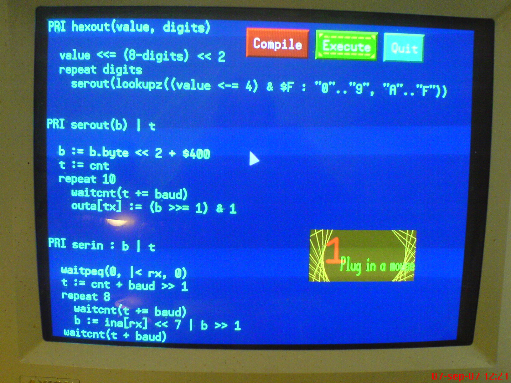
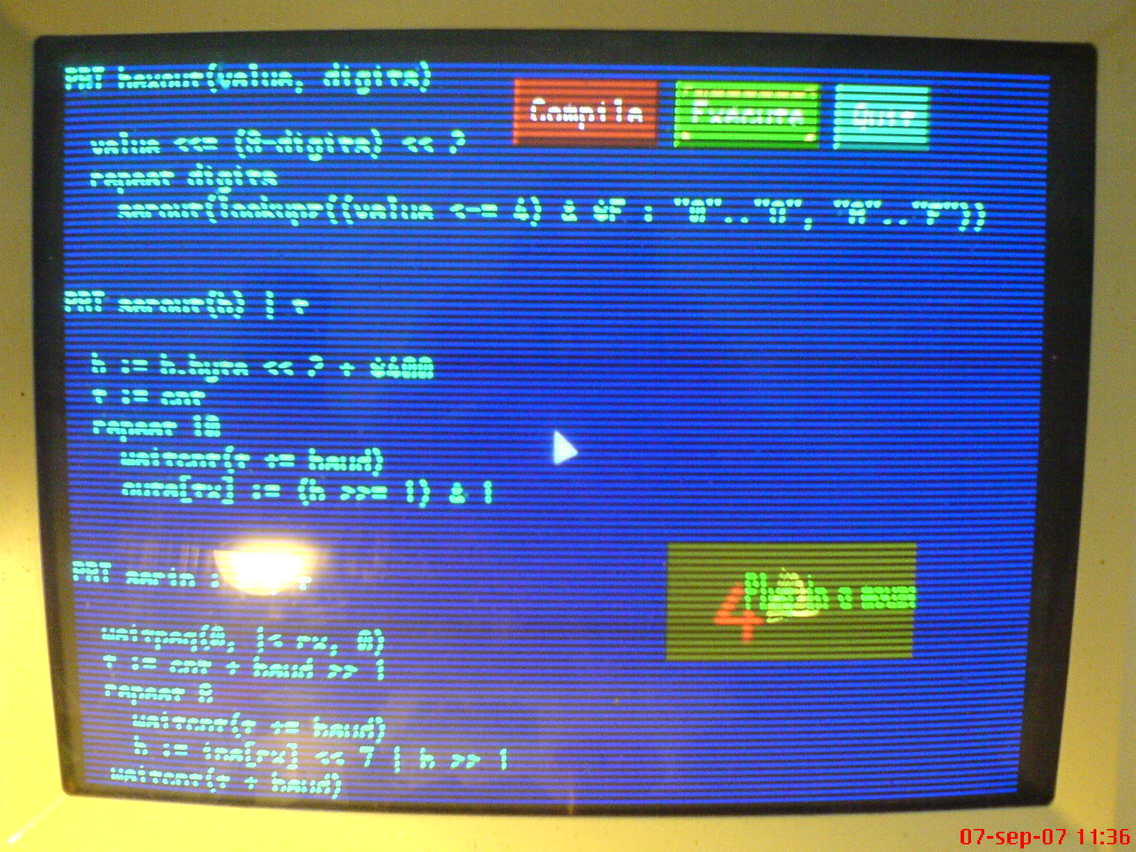
Study pictures One Cog have problem (With 120MHz) btu Propeller still run and I am Happy!
This mach more than I wanted!
▔▔▔▔▔▔▔▔▔▔▔▔▔▔▔▔▔▔▔▔▔▔▔▔
Sapieha
One off my test’s is speed and vhat happen if I override it.
With 120 MHz (15 MHz cristal x 8) Propeler still run but have small trouble.
Not all Cogs run properly.
·
So my question to deSilva.
·
Can you help my writing one assembly code routine for Cog (I still study Propeller and still incompetence to do)
whom tests Cos and writing result in Hub Ram for Log to study diference on separate run for calculate fault accuracy.
·
Study pictures One Cog have problem (With 120MHz) btu Propeller still run and I am Happy!
This mach more than I wanted!
▔▔▔▔▔▔▔▔▔▔▔▔▔▔▔▔▔▔▔▔▔▔▔▔
Sapieha
1632 x 1224 - 334K
1632 x 1224 - 411K
Comments
Just a quick idea, have you tried with a 7.5Mhz crystal, and *16 PLL?
- the PLL's and all related electronics (counters etc)
- instructions that use the flags C Z etc. These are the critical path in correct instruction execution
- then memories start failing, so then no reliable instruction execution is possible
If you want fault tolerance, why look for the edge where things start to fail? At 80 MHz they are guaranteed to work, at a wide temperature range, at a wide supply voltage margin.··
I tried many crystl options.
I have documented it.
But I is not finish and report comme in END on this test.
I still study results and still have lot of work on it.
I mast write one routine to test completely COG and report it tu my.
But I stil learn mig Spin and Propeler assembly and for it I mast understand COG to 100% every smal pice of it.
This is time consuming.
Ned little help from Propeller people whom understand Propeller chip and how COG works.
▔▔▔▔▔▔▔▔▔▔▔▔▔▔▔▔▔▔▔▔▔▔▔▔
Sapieha
I now that PLL in Propeller have problem with more than 100MHz .
I now att PLL in high frequency modes fail but I mast for my project calculate it precisely and simulate every possibility
▔▔▔▔▔▔▔▔▔▔▔▔▔▔▔▔▔▔▔▔▔▔▔▔
Sapieha
In other words: measuring limits on one single IC is useless, if you really want to know about about limits you need a statistically acceptable lot, meaning several 10s to 100's if IC's. And the you get statistical numbers as a result: at a given supply voltage and temperature·1 prop out of ten can reach 120 MHz, 8 out of ten can reach 110.·Because the prop is manufactured in a mature, well known process (.35um I vaguely remember), the spread on parameters will not be very large, but it is there.·Some props will start failing at 110MHz, some can reach 120.
If you want to select props for certain tasks·(high speed, low·temperature,·low Vss), you have to identify the parts of the chip that are most likely to fail first·(oscillator, PLL, flags) and design a testprogram that exercises those parts.
▔▔▔▔▔▔▔▔▔▔▔▔▔▔▔▔▔▔▔▔▔▔▔▔
The more I know, the more I know I don't know.· Is this what they call Wisdom?
I planning tests on many chips to calculate precise statistics but first will have funktioning test programs
(self test programs for COG’s to test every pice of its structure)
Ps. Lots of chips so I have true statistical reference
▔▔▔▔▔▔▔▔▔▔▔▔▔▔▔▔▔▔▔▔▔▔▔▔
Sapieha
Post Edited (Sapieha) : 9/11/2007 1:55:55 PM GMT
Ok knowing all this, please try the test Baggers suggested. I bet it won't work. A better thing to do would be to measure the actual frequency the prop is running at. Color TV signal generation is quite sensitive to problems with the main clock so it's not surprising thats where problems are seen.
My 2 bits,
Marty
▔▔▔▔▔▔▔▔▔▔▔▔▔▔▔▔▔▔▔▔▔▔▔▔
Lunch cures all problems! have you had lunch?
Post Edited (Lawson) : 9/11/2007 2:18:41 PM GMT
Thanks for this fine pice bit of information.
I still discover my Propeler and all info on its functioning internal is welcome
▔▔▔▔▔▔▔▔▔▔▔▔▔▔▔▔▔▔▔▔▔▔▔▔
Sapieha
Partial report
·
To all what want to try more high a frequency.
Patallex is not responsible for problems in-process procesora higher frequency than 80MHz.
·
As I expected this not Propeller but 5 Volt regulator what drew anxieties to run Propeller in higher frequency.
After addition of the additional cooling and Tantalum of capacitor, Propeller work correctly at the frequency of 15MHz * PLL8.
▔▔▔▔▔▔▔▔▔▔▔▔▔▔▔▔▔▔▔▔▔▔▔▔
Sapieha
Post Edited (Sapieha) : 9/19/2007 8:02:25 PM GMT
As Lawson said, the PLL won't operate at 240 MHz. It won't be locking and therefore not clocking the propeller at 120 MHz. Your PLL (Phase Locked Loop) changes to a PSL (Phase Slipping Loop). :P
Stabilizing +/- at the Propellor with a 4,7 uF tantal and using a 16 MHz crystal, an LED blinks exactly 11 times as busy as with RCFAST setting.
I think selected specimen of the Propeller could do that (PLL = 256 MHz)
I shall let it run through the night...
Current:
128 MHz : 20.5 mA
64 MHz: 9.7 mA
32 MHz 7 mA
16 MHz 4.7 mA
16 MHz without PLL: 3.3 mA
RC CLOCK (12 MHz): 2.2 mA
all plus 10mA for the LED
Post Edited (deSilva) : 9/19/2007 10:49:02 PM GMT
I am quite interested in these results. It's very possible that the fab making the Prop has extended the limits of the chip a bit while optimizing yields.
I'd like to see some hard measurments of the frequency the Prop is actually operating.
If the prop under test runs code like this
thousandth_toggle(pin) | temp
  ''this method toggles a pin once every 1000 clock cycles
  dirA[noparse][[/noparse]pin]~~
  temp = CNT
  temp += 1000
  repeat
    waitcnt(temp)
    !outA[noparse][[/noparse]pin]
    temp += 1000
The frequency on 'pin' will be 1/2000 of the tested prop's clock speed it's actually running at. (and down in the 100's of kilohertz range) A lab frequency counter, DMM, or another propeller should be able to count this frequency exported from the prop under test.
fun stuff!
Marty
▔▔▔▔▔▔▔▔▔▔▔▔▔▔▔▔▔▔▔▔▔▔▔▔
Lunch cures all problems! have you had lunch?
Sorry my test program is not complete but picture is from my VGA scren.
··· Clk := clkfreq··· .....····· This is formula to display frequency.·····
▔▔▔▔▔▔▔▔▔▔▔▔▔▔▔▔▔▔▔▔▔▔▔▔
Sapieha
@ Lawson : This es exactly what I did for the posted results! However some monthes ago, I tended to your opinion wrt PLL, for opposite evidences.. A large variance with extraordinary good samples has to be expected, when the vendor does not make a systematic preselection...
Post Edited (deSilva) : 9/20/2007 6:11:40 AM GMT
Need one routin to calculate real COG speed.
If it is one who have it pleas publish it
Thanks
▔▔▔▔▔▔▔▔▔▔▔▔▔▔▔▔▔▔▔▔▔▔▔▔
Sapieha
thousandth_toggle(pin) | temp
  ''this method toggles a pin once every 1000 clock cycles
  dirA[noparse][[/noparse]pin]~~
  temp = CNT
  temp += 1000
  repeat
    waitcnt(temp)
    !outA[noparse][[/noparse]pin]
    temp += 1000
Another way is to input an external regular pulse that your program meters against it's own execution speed and displays the result on your display.
Thanks.
I think att your 2 metod is beter.
I wait just for my real Clock IC and will masure timing with it.
▔▔▔▔▔▔▔▔▔▔▔▔▔▔▔▔▔▔▔▔▔▔▔▔
Nothing is impossible, there are only different degrees of difficulty.
Sapieha
(1) without the PLL and
(2) afterwards with any PLL,
as I did
Any old fashioned stop watch will do
Nothing against Stop watch but I’am can’t sit at the system entire week without sleep, to do statistics.
▔▔▔▔▔▔▔▔▔▔▔▔▔▔▔▔▔▔▔▔▔▔▔▔
Nothing is impossible, there are only different degrees of difficulty.
Sapieha
I typically run the Propeller at 96MHz using a 6MHz crystal and PLL 16 with no problems. And I've done this with numerous boards that I am using for the Propeller Book. Using a 6MHz crystal or oscillator combine with assembly language provides more than enough speed and is much faster than any mircocontroller when you use multiple COGs. If you using communications, video, or broadcast video, you'll have to tweak the routines to attain the proper frequency or speed.
Regards,
Oliver
You Said stop watch. you had on an idea such ?
Times of stone already a long ago elapsed.
Ps.My problem I can’t buy Press-n-Peel film in Sweden.
▔▔▔▔▔▔▔▔▔▔▔▔▔▔▔▔▔▔▔▔▔▔▔▔
Nothing is impossible, there are only different degrees of difficulty.
Sapieha
Post Edited (Sapieha) : 9/22/2007 9:39:27 AM GMT
It is a very academic investigation... The maximum speed of a device is principally limited by the power dissipation (going up somewhat quadratically) and the production and selection process. Parameters of production are phases of the moon etc...
Parallax guarantees the work of the Propeller upto 80 Mhz (and also with a 10 MHz crystal, which are to different kettle of fish). When a company makes no (A-) pre-selection then a wide, but arbitrary peformance deviation is possible. So we have most likely the situation:
- 80 MHz (8x10 or 16x5) works always
- 96 MHz (16x6) works in many cases
- 120 MHz (8x15) works in some cases
Sapieha has made the interesting observation from his former experiences, that a PLL needs a quite stable power supply and in marginal cases a signal conditioning (i.e. a "refresh").
When using PLL16X the PLL is most likely directly connected to complex circuitry, whilst using PLL8X the divider will perform this signal refresh more reliably.
So it is possible that 8x20MH can work, bit 16x10Mhz never will...
I would have the over-clocked propeller output a square wave signal and use another to read that signal and determine the frequency. Seems so much easier to me.
During the last 15 minutes I have set-up two 40p-DIP propellers on a 640p 2.75 € solderless breadboard and connected some parts you will learn about during the next weeks from Franz Achatz
I am just making a nice diagram, utilizing the graphics possibilities of Ariba's PropTerminal
Thanks.
To ALL:
As in the first answer in this thred I said It of is of upp to customer decision or wants to try
·but Parallax of not carry then responsibility for a product.
Ps.
Testifies only to high quality of product.
▔▔▔▔▔▔▔▔▔▔▔▔▔▔▔▔▔▔▔▔▔▔▔▔
Nothing is impossible, there are only different degrees of difficulty.
Sapieha
Post Edited (Sapieha) : 9/22/2007 2:22:07 PM GMT
btw: I like your sig
Does you not think that it is better to pass that Propellor its work.
Having so Fine of procesor with such force of count why I must sit and look after all of time what he does.
It will be nothing well the written program in ASM for COG with cooperation with RTC and drafting of counts in memory of RTC of the system from all of period of test.
Transfer of these information to Exel and there are complete statistics of work of Propellor from the period of test.
Without the necessity of sit and supervisions.
▔▔▔▔▔▔▔▔▔▔▔▔▔▔▔▔▔▔▔▔▔▔▔▔
Nothing is impossible, there are only different degrees of difficulty.
Sapieha
This simple code is going to toggle pin 0 at F/8, where F is the propeller clock freq, add a couple of NOP before and after the xor to half the freq. Or use the internal counter instead
You can capture that with another propeller and count the rising or falling flanks... no problem using the propeller built-in capabilities.
edit: fixed jump, too bad asms are never compatible [noparse]:)[/noparse], thx deSilva
Post Edited (Ale) : 9/22/2007 7:54:28 PM GMT