NEWBIE: Reset pin problems
Hi guys, having great fun with my Basic Stamp BS2e, done some electronics in the past but I'm very rusty!
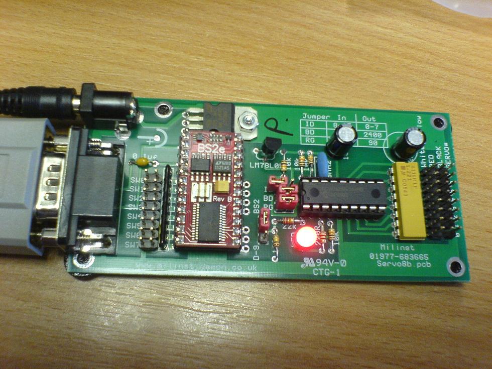
I'm using my BS2e on a custom board by a UK company called Milford Instruments - the board is designed to control 8 servo's for animatronics displays, and the stamp plugs into a normal 24 pin DIP socket.
My problem is, the board itself does not provide access for pin 22, the RES pin. I know that it will cause a reset when the supply to the stamp drops below 4.2 volts, and that it is possible to wire this up to a switch to provide a reset function, but I can't get to the pin to do it!
Is it possible to wire a normal IO pin to force RES low to make a reset button? I know that my code would have to check for this in a loop, but that isn't a problem.
Or, is there any other suggestions about how I could get access to this pin safely, without desoldering the board?
edit: Please see the attached image for photo of the board showing how pin 22 is not easily accessible.
Many Thanks in advance,
Morrolan
Post Edited (Morrolan) : 9/10/2007 12:38:58 PM GMT


Comments
In order to use an I/O pin to reset the BASIC Stamp that I/O pin needs to be connected directly to the I/O pin. The I/O pin should stay in input mode until you’re ready to reset the BASIC Stamp. At that point you can make the I/O pin output LOW and the BASIC Stamp will reset, also returning the I/O pin to an input. I hope this helps. Take care.
▔▔▔▔▔▔▔▔▔▔▔▔▔▔▔▔▔▔▔▔▔▔▔▔
Chris Savage
Parallax Tech Support
I'm sorry but I'm still a little confused - you say that the I/O pin needs to be connected directly to the I/O pin?. From that do you mean that the I/O pin should be directly connected to pin 22?
Sorry if I'm still a little confused
Many thanks in advance,
Morrolan
▔▔▔▔▔▔▔▔▔▔▔▔▔▔▔▔▔▔▔▔▔▔▔▔
Chris Savage
Parallax Tech Support
I/O pin and the reset pin. Just in case the I/O pin is accidentally
made a high output.
regards peter
Assuming that the capacitors are connected correctly between the ATN,VSS, and DTR of your serial connection,
then forcing the ATN (pin #3) HIGH·will cause a complementary reset to the Reset (pin #22) on your Stamp.
▔▔▔▔▔▔▔▔▔▔▔▔▔▔▔▔▔▔▔▔▔▔▔▔
Beau Schwabe
IC Layout Engineer
Parallax, Inc.
Once I do this, how would I connect Pin 22 to a button to force a reset? Do I need a button or switch that is normally closed (push to break) switch connected to VDD to force the pin low?
Kind Regards,
Morrolan
Post Edited (Morrolan) : 9/11/2007 1:08:42 PM GMT
You'd follow the same schematic as in the BS2p Demoboard for the reset switch.· Use a Normally Open switch between Vss(Pin# 23·or Pin# 4)·and Reset (Pin# 22).
http://www.parallax.com/dl/docs/prod/stamps/BS2pDemoCschem.pdf
▔▔▔▔▔▔▔▔▔▔▔▔▔▔▔▔▔▔▔▔▔▔▔▔
Beau Schwabe
IC Layout Engineer
Parallax, Inc.