

Need suggestions for LCD display project.
 Bean
Posts: 8,129
Bean
Posts: 8,129
Hi all.
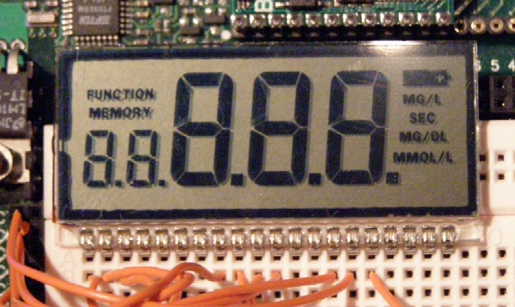
I have over 800 of these displays. They were originally for a blood meter.
They are 2.25" long and about 1" high.
They are just the LCD glass, but I have written a SX/B program to drive them.
Since they need almost no power, I would like to use an SX clocked very slow (32K) and use a 2032 battery for power.
But here's the problem: Do I make a board that accecpts data from a microcontroller, or do I make a board that does something on it's own (counter, timer, etc) ?
I'm looking for ideas of what to do with these.
Any ideas ?
Bean.
▔▔▔▔▔▔▔▔▔▔▔▔▔▔▔▔▔▔▔▔▔▔▔▔
The first rule to being successful is "Learn from your mistakes",
The second rule is "Be willing to make mistakes"
- - - - - - - - - - - - - - - - - - - - - - - - - - - - - - -
www.hittconsulting.com
750 x 447 - 319K
Comments
▔▔▔▔▔▔▔▔▔▔▔▔▔▔▔▔▔▔▔▔▔▔▔▔
It's Only A Stupid Question If You Have Not Googled It First!!
If you could lose the text (specific to its original function) and the decimal points, you might be able to turn it "upside-down" and make it talk to the SX in the Parallax GPS module and provide a simple Degree (3 large digits), Minutes (rounded to 2 digits and using the small numbers) display and cycle between·LAT and LONG readings.·Don't know how you would indicate N-S, E-W though. Maybe put a mask on the display and use the decimal points under·a mask of·· ·"N···· S···· E····· W" ·(there are 5 decimal points on the display).
Just some simi-random thoughts. Good luck.
Steve
Post Edited (Duffer) : 9/6/2007 11:13:40 PM GMT
You might consider making a SX based analog sample and display device. I am thinking of something that could be used to log temperature, humidity, pressure, etc. every T time intervals. The user could set the value of T. The little digits could display the sample number. The big digits could display the recorded value.
Or...
You could also make a Time-of-Event type of logging device. The user could connect a trigger signal such as an over temp. alarm or a door open sensor, etc. The device would log the time of each trigger event and display it when requested. The little digits could indicate the event number and the big digits could indicate the time using a decimal place as a PM indicator and one as a ten's place for the hour. Or maybe you could have the leftmost digit alternate between 1 and 0 for 10, 1 and 1 for 11 and 1 and 2 for 12. Of course you would need to include a blank period as well to make the flashing evident. Otherwise the flashing of 1 and 1 might not be noticed making it hard to distinguish from a normal 1!
I think it would definitely be great to be able to hook either of those devices to a computer to download the data and possibly adjust some of the operating parameters of the device. I also think there would be value in creating a display controller to be used with another micro-controller.
I do not know if any of those ideas will be profitable enough to recoup design costs. They are just ideas!
- Sparks
I remember in my·2nd year in college, I built a reaction timer game with my professor (8086 assembly code based) that gives me ideas for rebuilding it using an sx28 and an LCD like yours. It is still on display at the college today. It used pushbuttons from a frogger game (pinball side style). It is very smart to start at a random time once started and you press the stop button to have the smallest reaction time like gaime.
http://www.sunybroome.edu/~ieee/projects.htm
(2nd link down for "Reaction Timer")
I'll sum it up:
IF you make it generic, I'll buy 4 or 5
IF you make it single use, well, then, I guess I'll just be buying 1 or maybe 2 if I like the project.
You said: "Any ideas?"
These were mine.
▔▔▔▔▔▔▔▔▔▔▔▔▔▔▔▔▔▔▔▔▔▔▔▔
I'm not scared of your robot. I'm covered by Old Glory (youtube)
Anything I make will be open source so it can be "hacked" into whatever you want.
All good ideas so far, I think a thru-hole kit might make sense to keep the costs down. There is only the LCD, an SX28 and a some resistors and caps.
Bean.
▔▔▔▔▔▔▔▔▔▔▔▔▔▔▔▔▔▔▔▔▔▔▔▔
The first rule to being successful is "Learn from your mistakes",
The second rule is "Be willing to make mistakes"
- - - - - - - - - - - - - - - - - - - - - - - - - - - - - - -
www.hittconsulting.com
·
Whether you're testing RS232 serial outputs, or a crystal oscillator, or counter, or almost any sort of logic from a PC parallel port, or an SX, or propeller, or discrete circuit, it turned out to be really helpful to be able to visually see an indication of whether or how fast how the logic is clocking.
So I'd suggest making a debugging tool like that. Make a protected input so you can attach just about any logic or power source to it without damaging it. Have the input power a counter that drives the LCD. Have an LCD reset button to zero the counter. Have a level LED (or another part of the LCD) to show the static level at the input. And that's it. Keep it really simple.
Fast response would be nice, like up into the megahertz range, and that may be a problem if you want to keep the clock speed slow for low power consumption, but I guess response speed vs. power is a tradeoff that has to be made.
Bean.
▔▔▔▔▔▔▔▔▔▔▔▔▔▔▔▔▔▔▔▔▔▔▔▔
The first rule to being successful is "Learn from your mistakes",
The second rule is "Be willing to make mistakes"
- - - - - - - - - - - - - - - - - - - - - - - - - - - - - - -
www.hittconsulting.com
Frank
▔▔▔▔▔▔▔▔▔▔▔▔▔▔▔▔▔▔▔▔▔▔▔▔
The more I look for common sense in the world...
the more·I·find how un-common it is.
·