

What transistor should I use?
 MarkS
Posts: 342
MarkS
Posts: 342
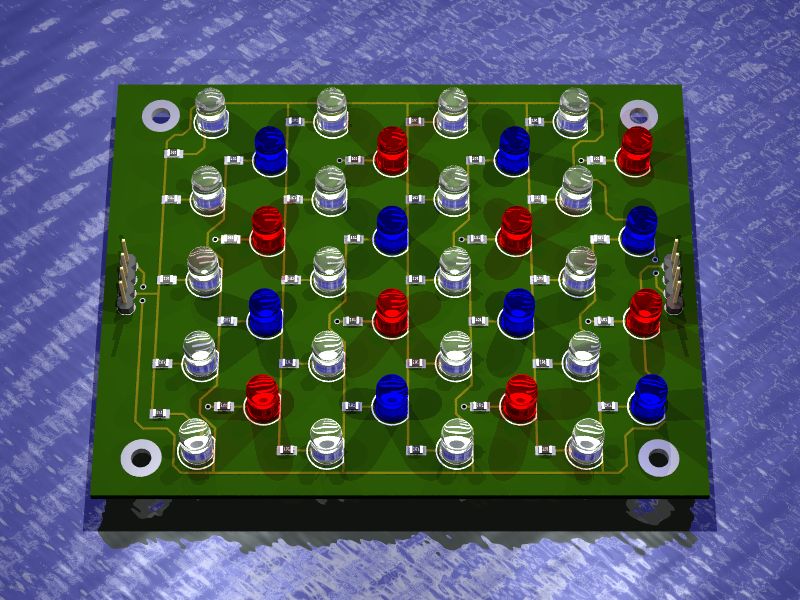
I'm designing an LED-based lighting system for an aquarium. Each light board will have 20 white LEDs, 8 blue LEDs and 8 red LEDs. The white and blue will be controlled by a microcontroller (probably a Prop) and the red will be controlled by a manually operated switch. The white and blue LEDs are grouped, so one microcontroller I/O pin for white and one for blue. The light boards can be daisy-chained if more lighting is needed.
The microcontroller is needed to produce a PWM signal to the LEDs to increase and decrease the brightness to simulate sunrise/sunset and moon phases. The light boards will have their own dedicated power supply, outputing 5V at 1A. The transistor needs to be able to handle 2A max and the PWM signal. I was thinking of using the 2n2222, but it is only rated to 100mA. What would be a better choice? The Darlington array that Parallax offers is out as it can only handle 1A, has 6 more transistors than I need and the voltage drop is far too high.
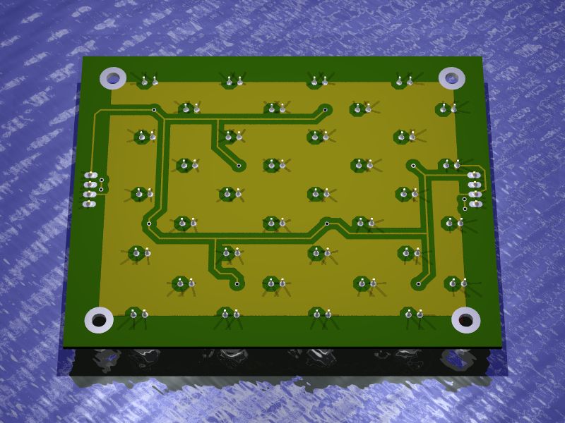
I've attached a pic of what the light board will look like. The circuit is visible and self explanatory.
Thanks,
Mark
The microcontroller is needed to produce a PWM signal to the LEDs to increase and decrease the brightness to simulate sunrise/sunset and moon phases. The light boards will have their own dedicated power supply, outputing 5V at 1A. The transistor needs to be able to handle 2A max and the PWM signal. I was thinking of using the 2n2222, but it is only rated to 100mA. What would be a better choice? The Darlington array that Parallax offers is out as it can only handle 1A, has 6 more transistors than I need and the voltage drop is far too high.
I've attached a pic of what the light board will look like. The circuit is visible and self explanatory.
Thanks,
Mark
800 x 600 - 105K
800 x 600 - 78K
Comments
Do the Prop's pins initialize in input mode? The LED control pins will only be set for output in software.
Post Edited (MarkS) : 8/31/2007 8:26:47 PM GMT
How did you make those cool sketches of the light board? They are amazing. This is a very interesting sounding project.·Hope you tell us more as you get it together.
▔▔▔▔▔▔▔▔▔▔▔▔▔▔▔▔▔▔▔▔▔▔▔▔
Whit+
"We keep moving forward, opening new doors, and doing new things, because we're curious and curiosity keeps leading us down new paths." - Walt Disney
Post Edited (Whit) : 8/31/2007 9:06:25 PM GMT
-Phil
▔▔▔▔▔▔▔▔▔▔▔▔▔▔▔▔▔▔▔▔▔▔▔▔
Yeah, that's what I found out. I was going to use a stamp first, but I'll need at least two PWMs going at once. Looks like I'll need the Prop. Not a problem though. The Prop is cheaper and just as easy to develop for.
I used Eagle to layout the board and Eagle3D to convert it to 3D. Povray is used to render the 3D file.
I can tell you as much as you want to know right now.
Post Edited (MarkS) : 9/1/2007 12:37:55 AM GMT
It is just always amazing to me how folks use their electronics/programing skills around other things they are interested in. Like the guys who do rocket circuitry or your aquarium light project. I am still amazed at the versatillity of some these inexpensive controllers and just all they can do.
▔▔▔▔▔▔▔▔▔▔▔▔▔▔▔▔▔▔▔▔▔▔▔▔
Whit+
"We keep moving forward, opening new doors, and doing new things, because we're curious and curiosity keeps leading us down new paths." - Walt Disney
In case you still have yearnngs for the Stamp's simplicity, you can use the MoBoStamp-pe and get up to four PWMs going at once. Moreover, these can drive your MOSFETs directly, in the background, without Stamp intervention.
-Phil
The light boards will be mounted in individual plastic cases in the aquarium hood. I'll either use ribbon cable and headers as jumpers between each board or I use male/female headers and they'll connect together snugly. The controller box will be outside the hood. It will be awhile, but I'll post pics as soon as possible.
There are nearly an infinite number of uses for chips like the Prop and Stamp. It really has opened the door for people that have some electronics skills (like myself) an want to put them to use. I'm building a microcontroller board based on a Motorola 68000 processor as an educational exercise and its a real challenge. There are just so many different parts needed, even just to power up the processor. When you factor in the logic, strange protocols and "standard" pin names, coupled with antiquated parts, this has really been difficult. I'm not an engineer, if I were one I'd be done already, so I can fully appreciate why microcontrollers are so popular.
Thanks, but no. Every time I get the urge to use a Stamp, I find another reason to stick with the Propeller. Its just plain better and a heck of a lot cheaper!