

Propeller DEMO: Micro Servo (torque proportional) Actuator
 Beau Schwabe
Posts: 6,576
Beau Schwabe
Posts: 6,576
Any of·you that are into micro RC flying will appreciate this.· And before I start·Graham Stabler deserves the original credit for documenting this design.
·
http://www.rcgroups.com/forums/attachment.php?attachmentid=905466
·
...even though this type of servo can be purchased for under $12 here...
·
http://www.micronradiocontrol.co.uk/plantraco_radio.html
·
...the satisfaction of building one can't compare.· By comparison though, the one I built is quite a bit bigger.
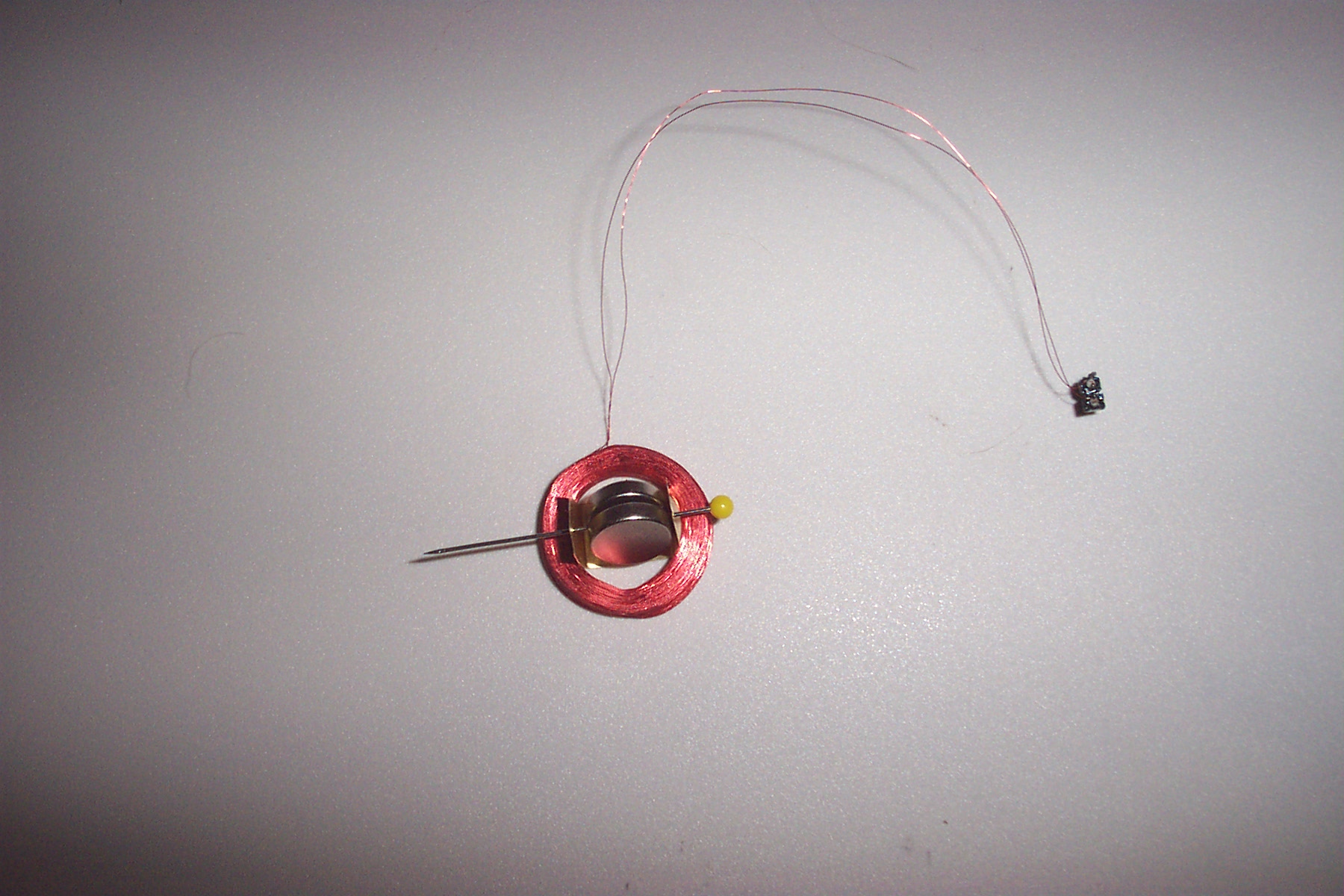
I just wanted to see how well it actually worked (works very well by the way)...The coil dimensions·measure in at 17mm inner diameter 25mm outer diameter, and a·height of 5mm weighing in at 11.34 grams... compare that to Graham's design ... 5.4mm inner diameter 8mm outer diameter, and a height of 5.5mm weighing in at 1.1 grams
Edit: The difference of almost 10x the weight actually makes sense... not counting the weight of the magnets, and using pi*r^2*h to determine the volume of just the coils, Graham's coil has a volume of ... (3.14 * 4mm^2 * 5.5mm )·- (3.14 * 2.7mm ^2 * 5.5mm) = 150.5 cubic millimeters .... compared to the larger coil (3.14 * 12.5mm ^2 * 5mm) - (3.14 * 8.5mm ^2 * 5mm) = 1319.47 cubic millimeters.· Looking at just the coils, the larger coil is 8.76 times larger by volume than the smaller coil.
·
Anyway, there is nothing fancy with using these servos, as far as what you need in Propeller software, I just setup a PWM signal in differential mode running at a base frequency of 20kHz and programmed a few test patterns.
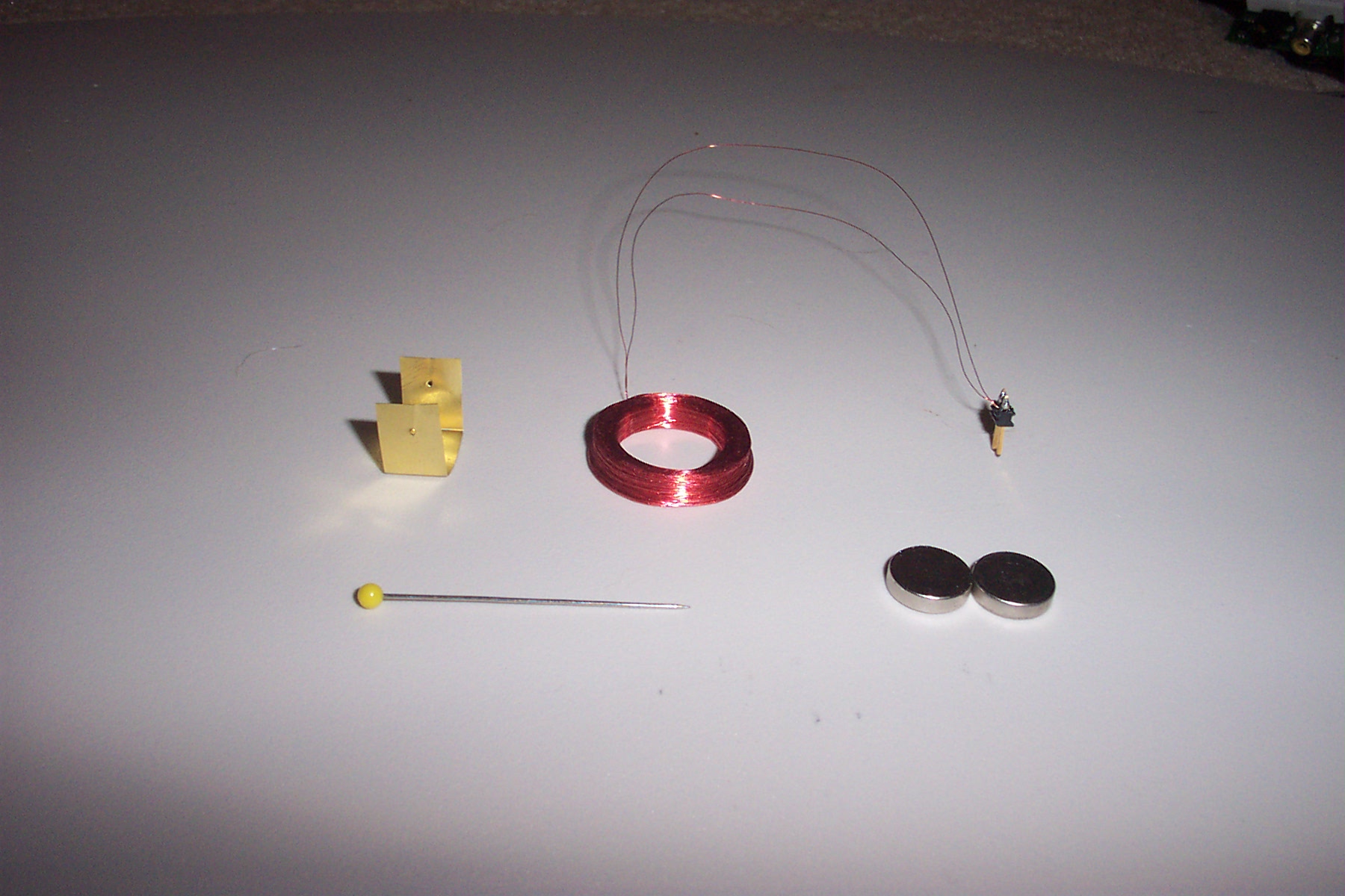
Coil dimensions:
700t x #38 copper enameled wire
17mm inner diameter
25mm outer diameter
5mm thick
Resistance = 70 Ohms·
·
Enjoy!
·
·
▔▔▔▔▔▔▔▔▔▔▔▔▔▔▔▔▔▔▔▔▔▔▔▔
Beau Schwabe
IC Layout Engineer
Parallax, Inc.
Post Edited (Beau Schwabe (Parallax)) : 8/28/2007 3:34:41 AM GMT
·
http://www.rcgroups.com/forums/attachment.php?attachmentid=905466
·
...even though this type of servo can be purchased for under $12 here...
·
http://www.micronradiocontrol.co.uk/plantraco_radio.html
·
...the satisfaction of building one can't compare.· By comparison though, the one I built is quite a bit bigger.
I just wanted to see how well it actually worked (works very well by the way)...The coil dimensions·measure in at 17mm inner diameter 25mm outer diameter, and a·height of 5mm weighing in at 11.34 grams... compare that to Graham's design ... 5.4mm inner diameter 8mm outer diameter, and a height of 5.5mm weighing in at 1.1 grams
Edit: The difference of almost 10x the weight actually makes sense... not counting the weight of the magnets, and using pi*r^2*h to determine the volume of just the coils, Graham's coil has a volume of ... (3.14 * 4mm^2 * 5.5mm )·- (3.14 * 2.7mm ^2 * 5.5mm) = 150.5 cubic millimeters .... compared to the larger coil (3.14 * 12.5mm ^2 * 5mm) - (3.14 * 8.5mm ^2 * 5mm) = 1319.47 cubic millimeters.· Looking at just the coils, the larger coil is 8.76 times larger by volume than the smaller coil.
·
Anyway, there is nothing fancy with using these servos, as far as what you need in Propeller software, I just setup a PWM signal in differential mode running at a base frequency of 20kHz and programmed a few test patterns.
Coil dimensions:
700t x #38 copper enameled wire
17mm inner diameter
25mm outer diameter
5mm thick
Resistance = 70 Ohms·
·
Enjoy!
·
·
▔▔▔▔▔▔▔▔▔▔▔▔▔▔▔▔▔▔▔▔▔▔▔▔
Beau Schwabe
IC Layout Engineer
Parallax, Inc.
Post Edited (Beau Schwabe (Parallax)) : 8/28/2007 3:34:41 AM GMT

Comments
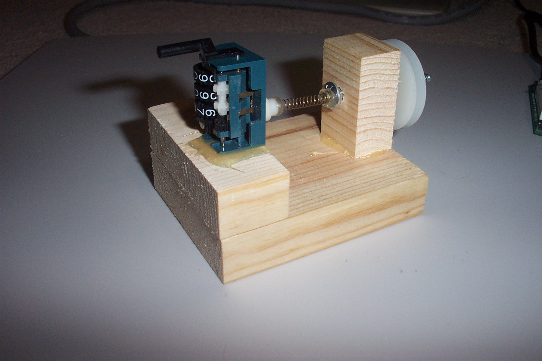
Where does one get a counter like that? And is that a ballpoint spring and hot glue differential?
Best described as "torque proportional" this can be confusing as a lone actuator will tend to not show its proportional nature, it will just swing to full travel but add a load (like airflow over a rudder) or a spring or magnet centering force and you get smooth motion as well as torque.
Graham
·
lol
·
The counter was salvaged from an "old" cassette player.... the spring simply acts like a universal joint to correct shaft misalignment. (<- human error)
To use it, the "bobbin" is made of a couple of nylon washers and spacers, simply attach a drill to the bobbin axle (right side of picture above).· With my counter, I have
manually determined that a count of 65 equals 100 turns, so I ran the thing until the counter reached 455 (or 700 turns).· Since the bobbin can breakdown and come apart,
the coil can be removed.· At this point, clear coat nail polish comes in handy to secure the windings.· You don't need much, and the coil will "wick" the nail polish nicely.
·
Tip: before winding the wire, wrap a small paper strip the width of your bobbin around the bobbin - this will make it easier to separate the bobbin from the wire when you are finished.
·
·
·
▔▔▔▔▔▔▔▔▔▔▔▔▔▔▔▔▔▔▔▔▔▔▔▔
Beau Schwabe
IC Layout Engineer
Parallax, Inc.
Post Edited (Beau Schwabe (Parallax)) : 8/27/2007 4:24:04 PM GMT
What sort of circuit arrangement did you use to power·the coil?
And at the end of the movie, it start to look like a motor. What's going on there?
Post Edited (Fred Hawkins) : 8/28/2007 12:24:35 AM GMT
There are a couple of coil/motor drive circuits here... http://members.aol.com/rchelicam/microszr/microszr.htm
...but I cheated and connected the Propeller pins directly to the coil.· At 70 Ohms, 3.3V is only 47mA required of the Propeller.· The Current Source/Sink per pin is rated at 40 mA.... close enough to the 47mA required by the coil in this application.
You could use reverse protection diodes (see attachment) in the form of a bridge rectifier, but I felt that the reverse breakdown diodes built into each of the I/O's on the Propeller·were adequate for this particular application.· The I/O's between two pins form a bridge rectifier to GND and the 3.3V supply·anyway through the protection diodes.
"And at the end of the movie, it start to look like a motor. What's going on there?"
You are correct... This is essentially the basics of a brushless DC motor.· What is missing from this verses a standard brushless DC motor is·the position feedback of the rotating magnet(s), usually accomplished with a hall effect sensor.· The fact that this actuator goes into a spin is when the·movement range is allowed to exceed 180 and the momentum of the magnet carries over into the next phase.· Limit the range of motion to right at or less than 180 deg and it won't do that.
▔▔▔▔▔▔▔▔▔▔▔▔▔▔▔▔▔▔▔▔▔▔▔▔
Beau Schwabe
IC Layout Engineer
Parallax, Inc.
Post Edited (Beau Schwabe (Parallax)) : 8/28/2007 2:54:18 AM GMT
Graham probably can point you at code that looks at the induced current coming back from the coil to determine position. (I've seen it but it's over my head.) Duh. Maybe that's the part about Hall effect stuff.
But I bet if you clamped the magnet and ran a guitar string over this thing you would have the basics for a magnetic pickup. Five more (or eleven for canceling hums) could end up as a the first prop guitar. Basses might be easier in every respect. Wiki on pickups does say 'a couple thousand turns of wire' though.
(Whispered: piezo pickup next? Grist for PEKits, yes)
You should go for it!· I mean "the first prop guitar"!
Here is a good source for rare Earth magnets that·are reasonably priced...
http://www.rare-earth-magnets.com/index.htm
The ones I used·for the actuator were (0.5 inch) ...
http://www.rare-earth-magnets.com/detail-ID-71.html
...but they make them much smaller.· The ones comparable to Radio Shacks 2 pack for ~$6 (0.25 inch), you can get·75 of them for just under $9
http://www.rare-earth-magnets.com/detail-ID-122.html
...even smaller (.125 inch), you can get 100 of them for $9
http://www.rare-earth-magnets.com/detail-ID-121.html
▔▔▔▔▔▔▔▔▔▔▔▔▔▔▔▔▔▔▔▔▔▔▔▔
Beau Schwabe
IC Layout Engineer
Parallax, Inc.
Have you actually tried this on a model airplane or car? It seems to me that without feedback, this thing's gonna cause problems. Imagine driving your model car at speed then slowing down. As you slow down the wheels will turn more and more for a given fixed amount of coil current. I think the effect would be worse on a model plane: Imagine trying to hold a fixed amount of rudder as airspeed changes over the rudder's surface, turning a turn or approaching a stall perhaps.
Regards, David
Post Edited (Drone) : 8/28/2007 6:06:28 AM GMT
These actuators work quite well for micro flight, where most of your feedback is visual based on what the plane is doing. In some RC cars this method is used for steering. For the matter regarding feedback, ·most of the hobby servo's don't provide feedback to the controller. You can tell any of them to go to a certain position, but you really have no way other than a visual indication that they have actually moved to where you wanted them to go.
Take into consideration that in some cases, the entire plane weighs less than the actuator that I built. This was more or less a test to see functionality of the Propeller with this type of actuator more than anything else. I should have built this with a .125 inch magnet. I bet I could get under 1 gram based on the mocked up design I currently have.
▔▔▔▔▔▔▔▔▔▔▔▔▔▔▔▔▔▔▔▔▔▔▔▔
Beau Schwabe
IC Layout Engineer
Parallax, Inc.
Post Edited (Beau Schwabe (Parallax)) : 8/28/2007 1:45:37 PM GMT
Countless times, as have many others. The reason it works is simple, there is feedback, its called your eyes. I have never seen a person fly by thinking "I need to keep 2mm of rudder deflection as I make this turn" you just add more/less as required to keep the craft on course. Of course it is not without any issues but in practise it works great.
For the record people are flying micro models with electric power IR control and an actuator on the rudder at under 0.5g all up weight!!
Graham
p.s. My favorite magnet supplier: www.engconcepts.net/
http://www.rcgroups.com/forums/showthread.php?t=596219
Use a single hall sensor for commutation.
Graham
It seems to me that the key concept that allows this actuator to be proportional is that the driving circuit is a pulse -- pwm. If it was just a simple switch -- power on, power off -- the swing would be to maximum each time. Speaking of which, can this maximum can be used to figure out the force created?