

SS relay w/ NC and NO terminals
 D Faust
Posts: 608
D Faust
Posts: 608
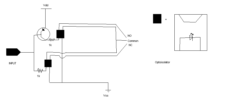
Would the following schematic work as a solid-state relay as shown?· The ssr with NC/NO terminal that I have seen are pretty expensive.
PS- Sorry for the bad schematic, I don't have special software, so I used MS paint.
▔▔▔▔▔▔▔▔▔▔▔▔▔▔▔▔▔▔▔▔▔▔▔▔
PS- Sorry for the bad schematic, I don't have special software, so I used MS paint.
▔▔▔▔▔▔▔▔▔▔▔▔▔▔▔▔▔▔▔▔▔▔▔▔
LOOKDOWN ThisThread, [noparse][[/noparse]Your_?, My_?, Cool_Thing], looknum
LOOKUP looknum, [noparse][[/noparse]1, 2, 3], subnum
ON subnum GOTO Hope_this_helps, Thanks!, WOW!!
END
Comments
If your input to your transistor is a pin from a chip, it is customary to put a resistor between the pin and the base of the transistor to protect the chip. A 220 ohm resistor would be common in most cases. It is un-clear what hardware you have and what you want your circuit to do....
Twisted Pair....
▔▔▔▔▔▔▔▔▔▔▔▔▔▔▔▔▔▔▔▔▔▔▔▔
-Phil
Update: My bad. My bad, bad, BAD! The original circuit is a great way to fry two optoisolators. Here's a better one. It's not perfect though. If the input is floating, both optos will be on.
'Sorry.
-Phil
Post Edited (Phil Pilgrim (PhiPi)) : 8/21/2007 5:25:04 AM GMT
▔▔▔▔▔▔▔▔▔▔▔▔▔▔▔▔▔▔▔▔▔▔▔▔
-Phil
▔▔▔▔▔▔▔▔▔▔▔▔▔▔▔▔▔▔▔▔▔▔▔▔
-Phil
▔▔▔▔▔▔▔▔▔▔▔▔▔▔▔▔▔▔▔▔▔▔▔▔
If, in fact, you added an additional resistor to the Stamp pin, both optos would always be on. This is because the resistor would share current with the opto that's supposed to be off.
-Phil
Post Edited (Phil Pilgrim (PhiPi)) : 8/21/2007 6:47:09 PM GMT
▔▔▔▔▔▔▔▔▔▔▔▔▔▔▔▔▔▔▔▔▔▔▔▔