Micro OLED displays - uOLED-128/160-GMD1 (4D Systems)
Since the cat is out of the bag .· ·From a Propeller forum post by "rj0_":
 · The attached ZIP file contains 4 demo programs, a text ReadMe and a color conversion program that lets you experiment with the color map for the displays (just a color utility).
A video of the Propeller demo can be seen at: http://www.youtube.com/watch?v=Aty0v51eo8I
The Stamp demos are nearly the same except that they are written in "pieces" because of the limitations for program storage (2K)·on the Basic stamp.
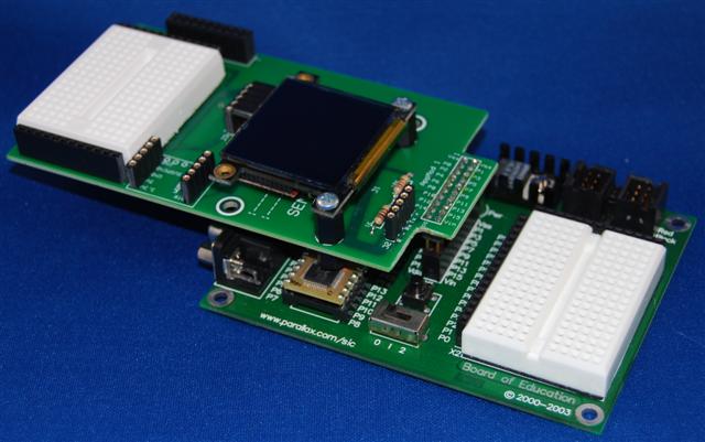
For the Basic Stamp, I'm using a BOE and various Stamp modules (BS2, BS2p, BS2px)·with an add-on "uOLED-AppMod" board pictured below. This is an add-on board of my own design that allows the uOLED displays (128 and 160) to be mounted in a number of convenient positions. The board connects directly to the AppMod connector on the BOE.
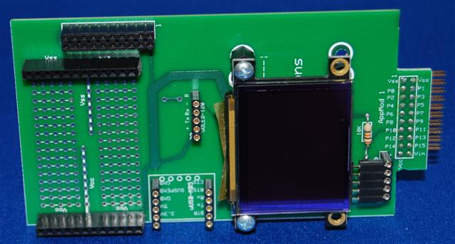
The AppMod connector is·extended·onto the board (to the right of the little breadboard area) so that other AppMod boards can be used while this board is installed. I've used pins 8(reset), 10 (Tx) and 11(Rx) as well as Vdd and Vss from the AppMod connector. Using these pins prevents pin conflicts with other AppMod boards (all that I know about anyway). So for example, you could use the uOLED AppMod board and still be able to use the eb-500 Bluetooth AppMod attached to the Aux AppMod connector. The board also provides a 10 pin header for the uUSB-MB5 (4D Systems)·USB to serial adapter so that the board (with display attached) can be used stand-alone without a uController.
The board provides a through-hole prototyping area at the "top" next to the Aux AppMod connector that allows you to bring signals from the AppMod on the BOE to the prototype area on the uOLED-AppMod. An optional mini breadboard (the same one that's used on the BOE) is also available and fits nicely between the Vdd and Vss headers available at the top of the board. This provides the same prototyping capabilities that you've become used to with the BOE.
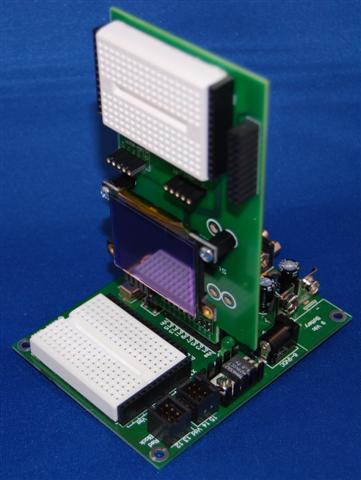
The board can be configured to mount either vertically or horizontally· on the BOE (different AppMod connector)· depending on your needs.
I hope you enjoy the demos and experimenting with the displays as much as I have.
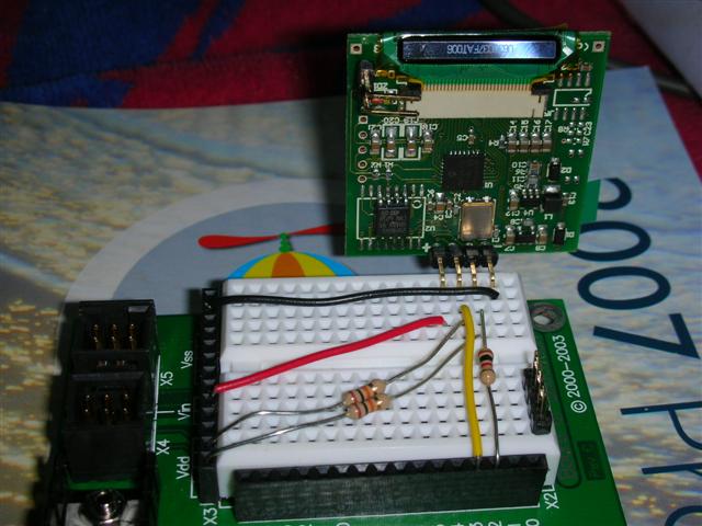
EDIT: The displays can be attached to the BOE prototype area without using my AppMod as shown in the added photo below.
Steve
Post Edited (Duffer) : 8/19/2007 2:40:09 AM GMT
 .· ·From a Propeller forum post by "rj0_":
Not to leave the Stamp folks out of the fun of using these new displays, I have written a number of PBasic demos for both the uOLED-128-GMD1 (which Parallax will be selling) and the uOLED-160-GMD1 (the 128's big brother).rj0_ said...
Oldbitcollector, Duffer, et. al.
Turns out the rumor is true... 4DSystems of Sydney has Parallax listed as a distributor. This was on my official wish list. And I would very much thank everyone for making it possible. And by not offering the carrier board, Parallax maintains its good corporate neighbor conduct.
Perhaps a new Parallax motto is in order? How 'bout... "If you are ready to earn, we are ready to churn."
Well done to THE Duffer.
I will be patiently waiting for a section in the Propeller Cook Book... The definitive do-it-yourself guide.
Rich
 · The attached ZIP file contains 4 demo programs, a text ReadMe and a color conversion program that lets you experiment with the color map for the displays (just a color utility).
A video of the Propeller demo can be seen at: http://www.youtube.com/watch?v=Aty0v51eo8I
The Stamp demos are nearly the same except that they are written in "pieces" because of the limitations for program storage (2K)·on the Basic stamp.
For the Basic Stamp, I'm using a BOE and various Stamp modules (BS2, BS2p, BS2px)·with an add-on "uOLED-AppMod" board pictured below. This is an add-on board of my own design that allows the uOLED displays (128 and 160) to be mounted in a number of convenient positions. The board connects directly to the AppMod connector on the BOE.
The AppMod connector is·extended·onto the board (to the right of the little breadboard area) so that other AppMod boards can be used while this board is installed. I've used pins 8(reset), 10 (Tx) and 11(Rx) as well as Vdd and Vss from the AppMod connector. Using these pins prevents pin conflicts with other AppMod boards (all that I know about anyway). So for example, you could use the uOLED AppMod board and still be able to use the eb-500 Bluetooth AppMod attached to the Aux AppMod connector. The board also provides a 10 pin header for the uUSB-MB5 (4D Systems)·USB to serial adapter so that the board (with display attached) can be used stand-alone without a uController.
The board provides a through-hole prototyping area at the "top" next to the Aux AppMod connector that allows you to bring signals from the AppMod on the BOE to the prototype area on the uOLED-AppMod. An optional mini breadboard (the same one that's used on the BOE) is also available and fits nicely between the Vdd and Vss headers available at the top of the board. This provides the same prototyping capabilities that you've become used to with the BOE.
The board can be configured to mount either vertically or horizontally· on the BOE (different AppMod connector)· depending on your needs.
I hope you enjoy the demos and experimenting with the displays as much as I have.
EDIT: The displays can be attached to the BOE prototype area without using my AppMod as shown in the added photo below.
Steve
Post Edited (Duffer) : 8/19/2007 2:40:09 AM GMT


Comments
▔▔▔▔▔▔▔▔▔▔▔▔▔▔▔▔▔▔▔▔▔▔▔▔
Chris Savage
Parallax Tech Support
I didn't mean to imply that the Stamps were deficient just because they only have 2K for program storage (BS2). I've also written a version of these same demos that runs on the BS2p and the BS2px that uses the multi-slot capabilities of those chips to load and run the whole demo by switching slots. Also, there are a number of ways to store images and data on external storage devices based on ones project requirements. I just like the fact that, with these displays, it's like getting a freebie (uSD slot and the command set to manage it) when you buy the display.
I certainly could have created MUCH smaller (and visually impressive) demo programs just by flipping throug images stored on the device's uSD card, but I didn't think that would help anyone who wanted to learn how to use the serial cammand set to actually create the images. For example, the 4th demo program (the one that draws what looks like some kind of pulse/respiration monitor), has 1 free byte remainig in program storage, but it shows how you can draw just about anything you want or need on screen. Other parts of the demo just draw colored circles and triangles and rectangles, those are important command to learn too.
In addition to demonstrating some of the capabilities of these little displays, I hoped that the demos would also be a learning tool for those that would like to add a color OLED display to their project (there's no need for everyone to make the same mistakes that I did when learning how these displays work). That's why I tried to use as many of the commands as possible in the demo. So that people could see how the different cammands were coded and the results on screen.
I did the same thing with the Propeller Object and the demo that uses it.
Steve
Post Edited (Duffer) : 8/20/2007 1:51:14 PM GMT