74HC595 problem
Hi all,
i got problem with my serial to parallel shift register 595,
while i've been testing it with separated LEDs (not 7segmentLED) on proto board everything was
working, but when i moved and soldered it, there started be a problem.
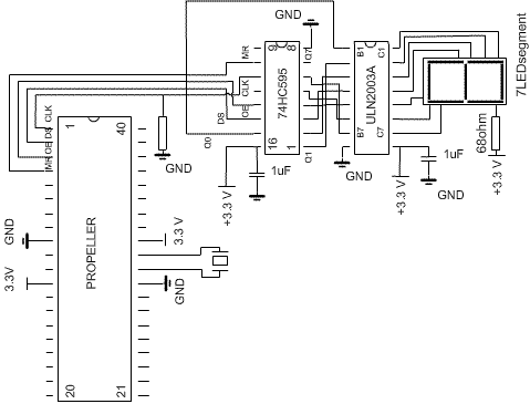
circuit is just driver for 7segment display and it can be
extended ... i did it for 3 segments
the problem is 595 works and sometimes not,
when not i have to touch 595 case with finger sometimes to get an output
for LCD segments, and sometimes it works itself ... i'm not satisfied
with this performance , if someone could have any idea how to fix it
please let me know...
A.
BTW does this engine support edit or delete POST ? i can't find it here, if yes please let me know


Comments
Sounds like maybe an input is floating, that is not connected, or not well connected. Bringing a something conducting, even a finger, can sometimes capacitatively move it into an enabled condition on a input pin.
▔▔▔▔▔▔▔▔▔▔▔▔▔▔▔▔▔▔▔▔▔▔▔▔
Harley Shanko
h.a.s. designn
Read wrong pin number.
▔▔▔▔▔▔▔▔▔▔▔▔▔▔▔▔▔▔▔▔▔▔▔▔
Post Edited (Skogsgurra) : 8/6/2007 10:31:45 PM GMT
ST_CP is not connected anywhere, does it have to be ? before i used to test it on proto board it has been working without ST_CP ... ? is that important for my problem to connect it ? from the timing diagram i can understand ST_CP should have reverse signal to SH_CP ...
it works this way, there are 3X 595, and 3 Segments, i have no problem to show correct number, i can see then bits fit, and every one of 595 provides correct outputs but to get it out io have to approach my finger, actually sometimes i don't need to touch it ...
in real, sometimes first 595 in a row of 3 show outputs signal and nex2 are disabled or, all of them provides signal... or first one no and 2 yes and last not... many combinations
▔▔▔▔▔▔▔▔▔▔▔▔▔▔▔▔▔▔▔▔▔▔▔▔
The word 'floating' in electronics can mean that an input is not electrically connected to a high or low state. Either tri-state or UNCONNECTED. But sometimes, say if a wire wrap wire were broken inside the insulation, there would be a capacitative effect for transitions, but wouldn't be biased to either ground or a high state.
The fact that your finger can start it working implies a very high impedance connection. Maybe a connection is off by one pin. Body capacitance can affect operations if a pin is 'floating' (not connected). Maybe time to use a ohmmeter/mulitmeter to check out your wiring.
▔▔▔▔▔▔▔▔▔▔▔▔▔▔▔▔▔▔▔▔▔▔▔▔
Harley Shanko
h.a.s. designn
My tip was not a "tip" - it is a fact and is what has to be done to get that 595 going.
▔▔▔▔▔▔▔▔▔▔▔▔▔▔▔▔▔▔▔▔▔▔▔▔
Please let us know what the problem is when you get your project running properly.
Inquiring minds want to know. (Even if one find it some 'stupid' misteak, as we all make from time to time; many times oftener!!)
Thanks.
ps - 'misteak' was intentional humor....
▔▔▔▔▔▔▔▔▔▔▔▔▔▔▔▔▔▔▔▔▔▔▔▔
Harley Shanko
h.a.s. designn
Answer : yes it can but i'm looking ahead and for my next step i'm going to need it, but it's another topic, i haven't solved that previous one... do you have any solution for my prob. ?
You have to clock the st_cp to get the information to the output. Did you?
▔▔▔▔▔▔▔▔▔▔▔▔▔▔▔▔▔▔▔▔▔▔▔▔
Not toggling pin 12 seems to put the output of the '595 into an high impedience state.
At least that's what I think this timing chart says. (Skogs, did I get that right? [noparse];)[/noparse]
Thanks God. Someone reads answers!
The transfer from shift register to output latches is done with the ST_CP (Storage Clock Pulse). The shifting as such is done with the SH_CP.
The timing diagram shows how data are transferred after each shift and that is sometimes meaningful. But in this case, I think that it is much better to do the complete shift first and then transfer so that the outputs stay calm during the shift (that's why you have the buffers in the first place).
There is probably another timing diagram somewhere showing this option.
▔▔▔▔▔▔▔▔▔▔▔▔▔▔▔▔▔▔▔▔▔▔▔▔
Your missing something Peto.
PIN 10 is MR(master reset) needs to be connected to VDD ( +) togeter with 16 (main + to the chip)
Also pin 13 OE ( Output enable needs to be connected to VSS (0V) together with pin 8 (main VSS of chip)
The Propeller signals to pin 11 (SH CP) and pin 12 (move Store CP) and pin 14 ( serial data)
PIN 12 to be pulled low with 10K
Your right in saying MR is not connected to the Prop but it needs to be tied to + volts otherwise it floats
same with pin 13 (OE tie it to 0V) ..floating pins means trouble...
Ronald Nollet Australia
Skogsgurra i do read all answers also yours, and i appreciate IT VERY MUCH (THANKS ALL of You FOR EVEN LITTLE IDEA) because now it may help to fix a new problem i've mentioned above