

FIXED! - Pressing F10 sometimes works, usually doesn't. _CLKMODE = XTAL1 + PLL1
 W9GFO
Posts: 4,010
W9GFO
Posts: 4,010
I'm working my way through the Propeller Manual. Right now I'm on page 133 and have run
into a quirk. When I press F10 to load Blinker2 into RAM it often doesn't execute as expected.
About 1 in 4 times it works properly. The other times a couple LEDs will turn on or some will flash
or nothing will happen. This only happens at PLL16X. Same behavior happens when loaded into eeprom
and the reset button is pressed.
Is this normal?

Post Edited (W9GFO) : 8/7/2007 3:40:42 AM GMT
into a quirk. When I press F10 to load Blinker2 into RAM it often doesn't execute as expected.
About 1 in 4 times it works properly. The other times a couple LEDs will turn on or some will flash
or nothing will happen. This only happens at PLL16X. Same behavior happens when loaded into eeprom
and the reset button is pressed.
Is this normal?
Post Edited (W9GFO) : 8/7/2007 3:40:42 AM GMT
spin
1K
Comments
Post edit - I asked this before he had the picture or code posted.
▔▔▔▔▔▔▔▔▔▔▔▔▔▔▔▔▔▔▔▔▔▔▔▔
E3 = Thought
http://folding.stanford.edu/·- Donating some CPU/GPU downtime just might lead to a cure for cancer! My team stats.
Post Edited (RinksCustoms) : 7/31/2007 6:17:51 AM GMT
Breadboards, especially used ones aren't terribly reliable. Parallax has designed a very robust chip with the propeller, while nothing is certain, the possibility does remain you may have gotten a defective PLL, but i have never heard of dud's in the forums.
If you need further help, you can IM me on yahoo. The button is just under my display picture on the right <---
▔▔▔▔▔▔▔▔▔▔▔▔▔▔▔▔▔▔▔▔▔▔▔▔
E3 = Thought
http://folding.stanford.edu/·- Donating some CPU/GPU downtime just might lead to a cure for cancer! My team stats.
Post Edited (RinksCustoms) : 7/31/2007 1:35:12 AM GMT
Thanks for looking,
Rich H
▔▔▔▔▔▔▔▔▔▔▔▔▔▔▔▔▔▔▔▔▔▔▔▔
Paul Baker
Propeller Applications Engineer
Parallax, Inc.
I would appreciate an explanation as to what you think is going on. I don't quite see why the crystal could be preventing the program from executing.
Here's what happens (only with PLL16X) in more detail;
Apply power to breadboard, hit F10, the program runs normally. So far it always works normally the first time loaded after it powers up.
Hit F10 again, this time nothing happens
F10 - now the first LED is on solid
F10 - runs normal
F10 - first LED is blinking rapidly
F10 - nothing
F10 - nothing
F10 - nothing
F10 - LEDs 1 & 2 blinking, LED 3 solid for a second then goes out
F10- runs normally
and so on...
▔▔▔▔▔▔▔▔▔▔▔▔▔▔▔▔▔▔▔▔▔▔▔▔
Paul Baker
Propeller Applications Engineer
Parallax, Inc.
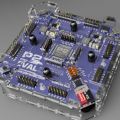
There is one red and one black wire going to the right from the crystal. I do not see any function there. Try removing them. They , together with the tracks, add capacitance that may be too much for the crystal.
▔▔▔▔▔▔▔▔▔▔▔▔▔▔▔▔▔▔▔▔▔▔▔▔
▔▔▔▔▔▔▔▔▔▔▔▔▔▔▔▔▔▔▔▔▔▔▔▔
E3 = Thought
http://folding.stanford.edu/·- Donating some CPU/GPU downtime just might lead to a cure for cancer! My team stats.
▔▔▔▔▔▔▔▔▔▔▔▔▔▔▔▔▔▔▔▔▔▔▔▔
The input pushbuttons on the right hand side are they connected properly
Do you have the resistors pulling the inputs low ..?
Maybe the inputs are just floating ( not connected to anything ?
TO me it appears that the resistors are on the wrong side of the pushbutton switch
Cheers
Ronald Nollet Australia
▔▔▔▔▔▔▔▔▔▔▔▔▔▔▔▔▔▔▔▔▔▔▔▔
That sounds very similar to an issue I was having with the PE Kit. It turned out I had fried something on the Propeller; a new one fixed it.
That was one of the first things I checked, the battery was reading just above 7 volts, I replaced it with a fresh one - no difference.
Funny you should mention that. When I first put those buttons in they weren't working right - they were floating. It turns out that the ground rail inside the breadboard was broken, that's why the black wire is there on the far right side.
·
Try running the attached program which is a variation of the MiltiCogExample.spin code published in the Objects lesson of the PE kit. Make sure a momentary button is connected to P23, pressing the button each time will start a LED with the blink rate of the duration between presses. Continued presses will extinguish the LEDs in reverse order. We have varified this code works properly on a PE kit we have here.
▔▔▔▔▔▔▔▔▔▔▔▔▔▔▔▔▔▔▔▔▔▔▔▔
Paul Baker
Propeller Applications Engineer
Parallax, Inc.
···· Dave
▔▔▔▔▔▔▔▔▔▔▔▔▔▔▔▔▔▔▔▔▔▔▔▔ D Rat
Dave Ratcliff· N6YEE
▔▔▔▔▔▔▔▔▔▔▔▔▔▔▔▔▔▔▔▔▔▔▔▔
Chip Gracey
Parallax, Inc.
The PE Kit instructions aren't showing any other capacitors that I know of.
▔▔▔▔▔▔▔▔▔▔▔▔▔▔▔▔▔▔▔▔▔▔▔▔
Well then, why is this not in the PE Kit instructions?
▔▔▔▔▔▔▔▔▔▔▔▔▔▔▔▔▔▔▔▔▔▔▔▔
I tried the MulticogObjectExample program, This program runs about 50% of the time that I hit F10, maybe less. However it doesn't seem to run as described. Each button press lights up a new led but once they are all blinking no amount of button presses extinguishes them.
Regarding the capacitors, I can see no capacitor on the schematic, drawing or photo that is included with the PE kit. I did grab a couple small capacitors that I had lying around and put them between GND and 3.3 right next to the chip but nothing would happen with them in place. Perhaps they were the wrong value, the ones I tried were .01uf.
▔▔▔▔▔▔▔▔▔▔▔▔▔▔▔▔▔▔▔▔▔▔▔▔
Paul Baker
Propeller Applications Engineer
Parallax, Inc.
Maybe, but everything else is on there.
Here's the insert that comes with the PE Kit. There's no capacitor like what you describe anywhere on the assembly diagram or the schematic.
If it's so important that the propeller could fail without it, that's a pretty major oversight.
A couple of time it has said that no propeller is found but if I unplug and plug back in the USB it works fine. I would think that we could rule out any problems on the PC end because I can load the program into eeprom, disconnect the prop plug and the same issues pop up. This time by hitting the reset button instead of F10.
I've tried many times both with and without a single .1uf cap accross 3.3 and GND, the only difference that I can see is that when running Blinker2.spin at PLL16X sometimes random LEDs will light up rather than just the first couple - which is what was happening before. Most often the first LED will be blinking or on solid.
Also, today the ratio of times that it runs correctly is better than before. The other day I was getting something like 1 in 4 times that it would run, today it's about 50-50. Again, the presence of the cap had no effect on this.
Either program, Blinker2 or MultiCog... work all the time when set to PLL8X.
Post Edited (W9GFO) : 8/1/2007 5:50:42 PM GMT