

Propeller RCFast oscillator as a function of temperature
 Paul Baker
Posts: 6,351
Paul Baker
Posts: 6,351
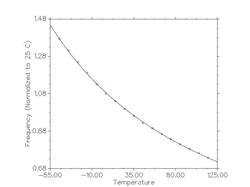
Here's a graph I threw together that shows how the RCFast's oscillator frequency changes over temperature. Since there is variability in the actual·values from chip to chip, I have normalized the frequency to the value produced at 25 C (room temperture).·I did this because I do not want people misinterpreting the graph, it is only meant to show how the frequency on any one Propeller will change over temperature. Those that want a fitting function, the following inverse quadradic was used to generate the line: y = 1 / (.9·+ .00385x +·5.39E-07x2)
The current sample set is 1, however this will be expanded before the graph is included into the datasheet.
▔▔▔▔▔▔▔▔▔▔▔▔▔▔▔▔▔▔▔▔▔▔▔▔
Paul Baker
Propeller Applications Engineer
Parallax, Inc.
The current sample set is 1, however this will be expanded before the graph is included into the datasheet.
▔▔▔▔▔▔▔▔▔▔▔▔▔▔▔▔▔▔▔▔▔▔▔▔
Paul Baker
Propeller Applications Engineer
Parallax, Inc.
800 x 600 - 7K
Comments
Could one determine this in software somehow, thus know about temp changes with no additional hardware? I know there would be no absolutes, without some reference, but that still leaves the delta.
▔▔▔▔▔▔▔▔▔▔▔▔▔▔▔▔▔▔▔▔▔▔▔▔
Propeller Wiki: Share the coolness!
▔▔▔▔▔▔▔▔▔▔▔▔▔▔▔▔▔▔▔▔▔▔▔▔
Paul Baker
Propeller Applications Engineer
Parallax, Inc.
▔▔▔▔▔▔▔▔▔▔▔▔▔▔▔▔▔▔▔▔▔▔▔▔
Propeller Wiki: Share the coolness!
▔▔▔▔▔▔▔▔▔▔▔▔▔▔▔▔▔▔▔▔▔▔▔▔
Paul Baker
Propeller Applications Engineer
Parallax, Inc.
Quattro
▔▔▔▔▔▔▔▔▔▔▔▔▔▔▔▔▔▔▔▔▔▔▔▔
'Necessity is the mother of invention'
▔▔▔▔▔▔▔▔▔▔▔▔▔▔▔▔▔▔▔▔▔▔▔▔
Paul Baker
Propeller Applications Engineer
Parallax, Inc.
That would be very nice to have for someone that is using the threshold voltage as a crude measuring tool. I have checked that for two batches and the typical voltage seems to be around 1.43 V at 3.3 V supply and not too much variation over the +10 to +30 centigrade range where I will use this technique.
(For those that think that I have gone mad: I do this to detect very fast spikes in the +/- 1000 V range. The detection circuit is a voltage divider and a bias network where I can adjust bias by outputting a variable voltage using PWM. I do not need better than around +/-50 V accuracy so the threshold method works quite well. And capturing the spikes using the counter makes it very fast. Faster than most high-priced comparators, actually.)
▔▔▔▔▔▔▔▔▔▔▔▔▔▔▔▔▔▔▔▔▔▔▔▔
Just my brain running on idle the last few minutes before I close the Helldesk and begin my weekend...
▔▔▔▔▔▔▔▔▔▔▔▔▔▔▔▔▔▔▔▔▔▔▔▔
Don't visit my new website...
Yeah my original thought of using the internal oscillator as a temperature gauge involved using a crystal until I realized that both would need to be accessible simultaneously.
▔▔▔▔▔▔▔▔▔▔▔▔▔▔▔▔▔▔▔▔▔▔▔▔
Paul Baker
Propeller Applications Engineer
Parallax, Inc.
Even if there are individual Vth variations between chips, it would be useful to have an "official" paper describing variation with temperature and also with supply voltage. In my application, there will always be one point where the thing is tested (manually) and then it can also be calibrated.
It has been mentioned that Vth is .5*Vcc, but that is not what I see. Most chips I have tested are 1.43 - 1.44 V at 3.30 V Vcc. It is difficult for me to test across many batches, I have only seen two so far. If there is an even bell shape around 1.65 V and I happened to find 1.43 - 1.44, will there also be 1.65 + (1.65-1.43) = 1.87 V individuals?
These data are important in some applications, but I do not expect any guaranteed values. Typical values and a possible range would be very nice, though.
Using the counters as glitch cathers is great. A lot faster than most comparators. Detecting pulses down to 25 ns width without any problems. Might even work for 12.5 ns. But haven't been able to test that.
▔▔▔▔▔▔▔▔▔▔▔▔▔▔▔▔▔▔▔▔▔▔▔▔
Some·parameters people would like to have are simply not possible to provide, it is not just temperature but process which determines the boundries. There are many variables to a process each which has a particular effect on the performance of the chip. Unless the structure is small enough to where we can model it in SPICE using the corner models provided by the foundry, the only way we could fully characterize the boundries of a chip are to have wafers produced at each permutation of variable boundries of the process. This would be a monumental waste of money because all the wafers would have to be thrown away after a few dies of each wafer were tested because they represent the outer limits of acceptabilty.
▔▔▔▔▔▔▔▔▔▔▔▔▔▔▔▔▔▔▔▔▔▔▔▔
Paul Baker
Propeller Applications Engineer
Parallax, Inc.
Post Edited (Paul Baker (Parallax)) : 7/27/2007 10:38:23 PM GMT
The values I have measured seems to be fairly constant over the limited temperature range I will use the device, so the calibration can probably handle individual variations very well.
Thanks again.
▔▔▔▔▔▔▔▔▔▔▔▔▔▔▔▔▔▔▔▔▔▔▔▔
▔▔▔▔▔▔▔▔▔▔▔▔▔▔▔▔▔▔▔▔▔▔▔▔
Paul Baker
Propeller Applications Engineer
Parallax, Inc.
Output drive is of much less concern. As long as you can drive an R2R ladder with R = 10 k without too much variation in Vhigh and Vlow, I am fine.
▔▔▔▔▔▔▔▔▔▔▔▔▔▔▔▔▔▔▔▔▔▔▔▔