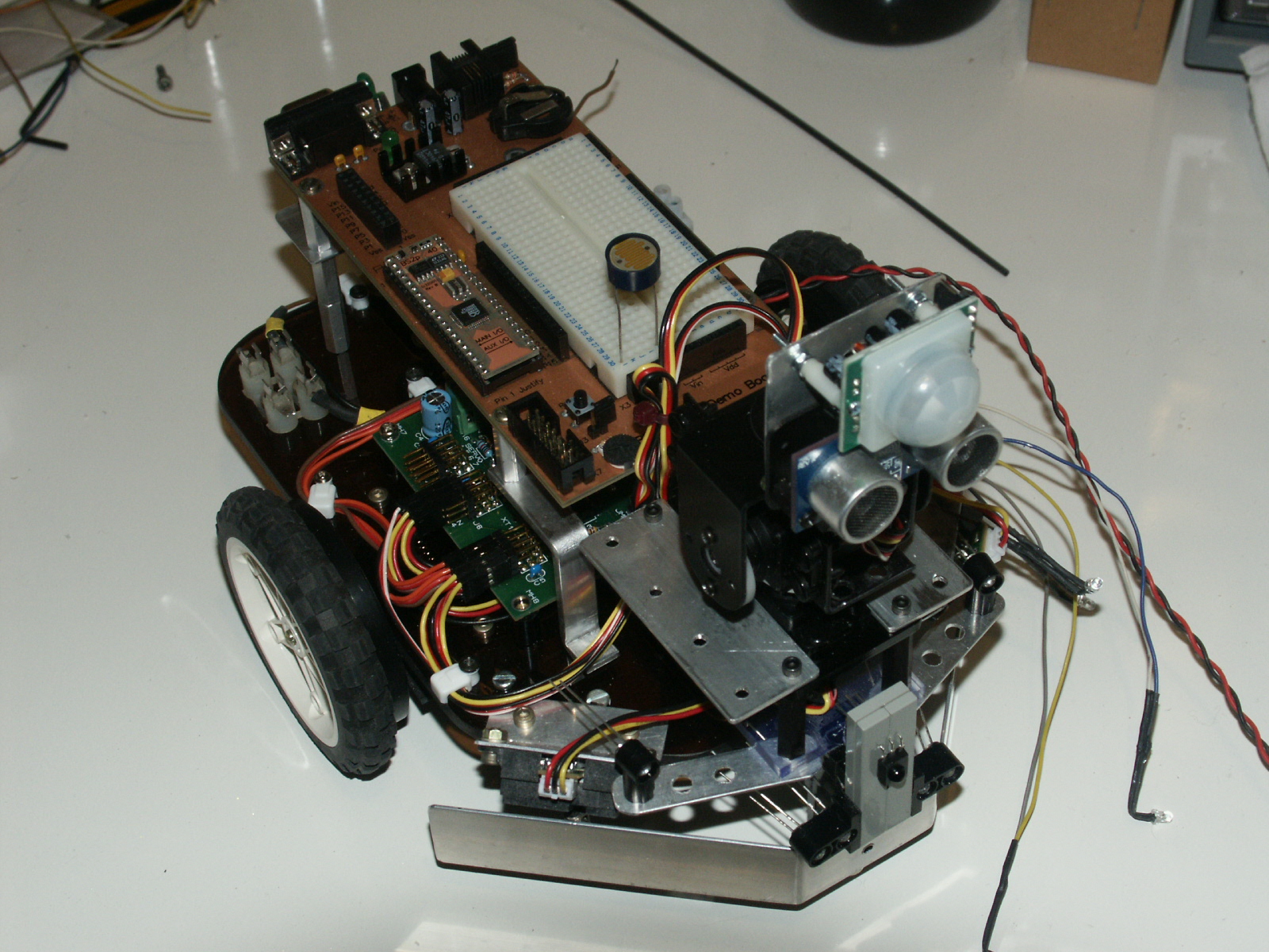
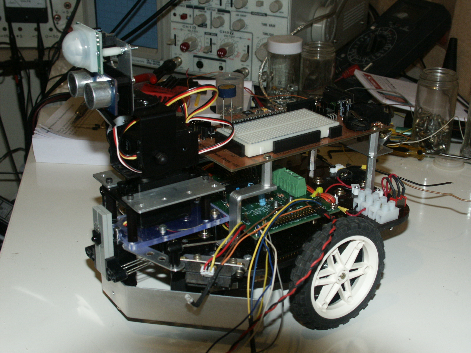
Robotic mobile base with lots of sensors
Please I need help with this mobile base in the coding area, I am using a BS2p40 with demo board and Bluebells design
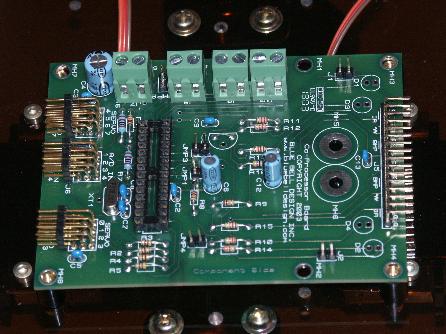
subsumption circuit board which has 8 servo inputs and 4 A/D inputs, The pbasic software at present runs the two servo
drive units, IRPD sensors and 2 bump sensors, However I have a number of other sensors which I would like to use and
I do not know where to insert the extra code in the subsumption architexture so that the sensors make the right servo commands.
Also I need the eminic speech chip to say which sensor is activated. Pir to say [noparse][[/noparse]Intruder detected] ect.
2 Bump sensors Programed
1 IRPD sensor Programed
3 GP2D12 sensors To program
1 PIR sensor To program
1 LDR Do not need to program, Used stand alone circuit, not connected to stamp for head lamps.
1 LCD display To program
1 Ultra sonic ping To program
2 Pan/tilt servos to program for ping U/S
4 white LED head lamps Do not need to program, Used stand alone circuit with above LDR, not connected to stamp for head lamps
1 Emic speech chip To program
2 drive servos Programed
Low battery indicator To program
So you can see I have my work cut out in the programing area, I don't think I will have any hair left after this project.
I can post the code that I am using at present and a pic of the robot. I am not sure how to integrate the code from the
sensors to the various movements of the servos, any help in this area would be greatly appreciated. I am learning pbasic
but being 56 yrs I do not find it easy to learn this, younger people seem to pick this sort of thing up easy.
Hardware is no problem for me but software is another thing.
Thanks in anticipation.
Stampnut.
Pics
1 Left side showing sensors
2 Right side showing sensors
3 Subsumption board
4 top view with subsumption board.
▔▔▔▔▔▔▔▔▔▔▔▔▔▔▔▔▔▔▔▔▔▔▔▔
Never give up when things go wrong.
Post Edited (StampNut2) : 8/7/2007 6:30:13 PM GMT


Comments
2. You need a topic title.
Yes, you need to post your code for us to be able to help you.
▔▔▔▔▔▔▔▔▔▔▔▔▔▔▔▔▔▔▔▔▔▔▔▔
Don't visit my new website...
▔▔▔▔▔▔▔▔▔▔▔▔▔▔▔▔▔▔▔▔▔▔▔▔
Never give up when things go wrong.
▔▔▔▔▔▔▔▔▔▔▔▔▔▔▔▔▔▔▔▔▔▔▔▔
Chris Savage
Parallax Tech Support
True programming is frustrating but soon you will learn how the Stamp works best for your project. Multitasking is going to become difficult because you have so many sensors and truly a Stamp won’t multitask. A Spin chip would be better for this project but if you are stuck on the STAMP then try writing little modules and test each one before moving on the next module. For example write a function that measures distance and test it. Then write code for turning the head and test it as well. Then after testing all the modules try tying them together.
Please post some code here for more help
▔▔▔▔▔▔▔▔▔▔▔▔▔▔▔▔▔▔▔▔▔▔▔▔
My web site -- > www.floodhound.com <-- take a look if you like
▔▔▔▔▔▔▔▔▔▔▔▔▔▔▔▔▔▔▔▔▔▔▔▔
Never give up when things go wrong.
Post Edited (StampNut2) : 7/26/2007 6:55:53 PM GMT
▔▔▔▔▔▔▔▔▔▔▔▔▔▔▔▔▔▔▔▔▔▔▔▔
Never give up when things go wrong.
Perhaps you should do some reading on subsumption programming. A search of the Internet shows thousands of hits.
Regards,
Bruce Bates
▔▔▔▔▔▔▔▔▔▔▔▔▔▔▔▔▔▔▔▔▔▔▔▔
▔▔▔▔▔▔▔▔▔▔▔▔▔▔▔▔▔▔▔▔▔▔▔▔
Never give up when things go wrong.
Post Edited (StampNut2) : 7/29/2007 5:51:29 AM GMT
It sounds like you need to re-think your design before proceeding further.
I have the two servo drives working plus IRPD and bump sensors, If no one knows where to insert the other sensors PLEASE can some one tell me where to insert the roaming with ping and the GD2P12 sensor code into the subsumption 1-5 level.
Thanks
▔▔▔▔▔▔▔▔▔▔▔▔▔▔▔▔▔▔▔▔▔▔▔▔
Never give up when things go wrong.
Post Edited (StampNut2) : 7/30/2007 6:27:20 PM GMT
▔▔▔▔▔▔▔▔▔▔▔▔▔▔▔▔▔▔▔▔▔▔▔▔
Never give up when things go wrong.
I tried looking at the url for the bluebelldesign but it is either offline or my ISP is having routing problems.... Maybe it will be fixed by the weekend.
It looks like you are doing a nice job on the construction of the robot and it should work out well as a platform to experiment on and learn more anout programming. For now just set aside some of the extra's (LCD, speech) and just start adding in one more sensor at a time. The approach I would take is to try inserting the code for your new sensors at different levels and see if it gives go the behaviors you expect. If not, move them to a different level and try again. Even robots that are built similar can act quite a bit different depending upon sensor placement, etc so you have to tweak your code for the robot it's running on. One resource you may want to pickup if you want to read a bit more on Subsumption is: "Mobile Robots Inspiration to Implementation" by Joseph L. Jones and Anita M. Flynn ISBN 1-56881-011-3 It has several examples which may help. They are written in Interactive C for a HandyBoard but the examples are still useful. If you find that the BASIC Stamp isn't quite fast enough then you could drop in an SX48 module in its place:
http://forums.parallax.com/forums/attach.aspx?a=13623
It can be programmed in SX/b (BASIC), assembly, and now there are a couple options for a C compiler. For now you should probably stick with what you've got but if you need more performance and control there are options.
For answers that directly relate to your program you'll probably get more responses if you ask focused questions on programming a particular sensor or output device. Also, if you can give more examples on what you want it to do and how you want it to behave ask which group of sensors would be the best ones to use for the way you want it to act.
Good luck,
Robert
Here is the link to Blue Bell Design: http://www.bluebelldesign.com/
Regards,
Bruce Bates
▔▔▔▔▔▔▔▔▔▔▔▔▔▔▔▔▔▔▔▔▔▔▔▔
▔▔▔▔▔▔▔▔▔▔▔▔▔▔▔▔▔▔▔▔▔▔▔▔
Never give up when things go wrong.
Taking a look at their docs does clarify some things. One the subsumption logic is built in to their co-processor chip and can automatically do some things depending upon the sensor readings that it is taking. That is an important point since many reading this may be under the impression that you are trying to read all the sensors and do the subsumption logic all within the BASIC stamp itself. That changes things a bit. Since you are offloading much of the work that will make it easier for the Stamp to do some higher level functions.
Does Blue Bell have a similar forum for users of its chip or an e-mail list that you can sign up? That would be the best place to ask about the particulars of using that co-processor. It has its own set of commands and even looking over the datasheet someone would have to try it out and work with it a bit to see how it really reacts before they could offer any decent suggestions on it's use. I expect that most people here would be more familiar with using the BASIC Stamp itself to check all the sensors and drive the servos, etc instead of using that particular chip.
Robert
Thanks
Mike
▔▔▔▔▔▔▔▔▔▔▔▔▔▔▔▔▔▔▔▔▔▔▔▔
Never give up when things go wrong.
▔▔▔▔▔▔▔▔▔▔▔▔▔▔▔▔▔▔▔▔▔▔▔▔
Never give up when things go wrong.
Post Edited (StampNut2) : 8/7/2007 7:00:12 PM GMT
Post Edited (Robostein) : 8/8/2007 3:41:58 AM GMT
www.winbond-usa.com/products/isd_products/chipcorder/datasheets/1400/ISD1400_Rev1.2.pdf
ISD speech chip selections
www.datasheetcatalog.com/informationstoragedevices/1/
My favorite ISD 5008
▔▔▔▔▔▔▔▔▔▔▔▔▔▔▔▔▔▔▔▔▔▔▔▔
Never give up when things go wrong.
Post Edited (StampNut2) : 8/8/2007 6:57:25 AM GMT
Gr,
Mightor
▔▔▔▔▔▔▔▔▔▔▔▔▔▔▔▔▔▔▔▔▔▔▔▔
| What the world needs is more geniuses with humility, there are so few of us left.
| "Wait...if that was a compliment, why is my fist of death tingling?"
| - Alice from Dilbert
▔▔▔▔▔▔▔▔▔▔▔▔▔▔▔▔▔▔▔▔▔▔▔▔
Never give up when things go wrong.
Hope this gave you some ideas. If not, don't hesitate to ask. Just so you know though, I won't be able to help you with the actual programming. I'll leave that as an exercise for the reader, hehe.
Gr,
Mightor
▔▔▔▔▔▔▔▔▔▔▔▔▔▔▔▔▔▔▔▔▔▔▔▔
| What the world needs is more geniuses with humility, there are so few of us left.
| "Wait...if that was a compliment, why is my fist of death tingling?"
| - Alice from Dilbert
▔▔▔▔▔▔▔▔▔▔▔▔▔▔▔▔▔▔▔▔▔▔▔▔
Never give up when things go wrong.
How about starting by developing your code one piece at a time. For example, first control the motors. Next, add a sensor and integrate it into your program. Continue on until it is too difficult, then add the BlueBell co-processor to take over the motors. That's going to solve a lot of timing problems. Don't try to do everything at once for now - just start writing code one small piece at a time. Use our Robotics book if you need help.
Ken Gracey
Thanks
Mike
P/s The GD2P12 sensors are connected to the A/D lines on the subsumption board.
▔▔▔▔▔▔▔▔▔▔▔▔▔▔▔▔▔▔▔▔▔▔▔▔
Never give up when things go wrong.
Post Edited (StampNut2) : 8/8/2007 6:55:38 PM GMT
I didn't look at your code yet, so I can't say whether or not it is appropriate to start over. What I was trying to convey, though, is that in my limited experience writing code I find it most productive to start with small pieces, adding features/sensors, with total project in mind the whole time. In this case, you've got this 20ms period to revisit the servos.
You are currently using our working code snippets, and you're trying to link them together. This is AOK and dangerous. It's acceptable if you understand how each piece works before you combine pieces of programs.
Ken Gracey
▔▔▔▔▔▔▔▔▔▔▔▔▔▔▔▔▔▔▔▔▔▔▔▔
Never give up when things go wrong.
It's not "dangerous" per se, but perhaps more inefficient to link lots of code together from different places. You will find that each example may use byte and word variables quite freely to showcase the example, and maybe they all use temporary variables as well. Combine all this "stuff" together and you get wastefullness and RAM shortage. For example, some programs we publish may have liberal use of DEBUG statements to show the sensor output on the PC. This could also consume lots of precious time along the way.
You just need to be aware of how you're mixing things up in the big pot. If each recipe has it's own share of peppers and butter and you add them together you might wake up late at night with a cholesterol problem and acid reflux. Think about the whole recipe and don't necessarily let the ingredients be additive. Understand what you're bringing into your main program from each recipe before you get carried away.
Others on this forum may be able to put this into words a bit better than I.
Ken Gracey
Parallax, Inc.
▔▔▔▔▔▔▔▔▔▔▔▔▔▔▔▔▔▔▔▔▔▔▔▔
Never give up when things go wrong.
▔▔▔▔▔▔▔▔▔▔▔▔▔▔▔▔▔▔▔▔▔▔▔▔
Never give up when things go wrong.