Current Meter Data Logger
I have read posts in the past and wondered myself how much power does a complex circuit that sleeps, wakes up and monitors various inputs use over time. I read a pdf on a system called SPOT. So I decided to try and roll my own current monitor data logger.
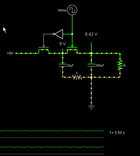
I am thinking about making a current meter to log total current used by battery operated circuits. The attached schematic shows 2 P channel mosfets that would be driven by a Uc. The triangle is an inverter so one of the fets is on and the other is off. I would then connect the output capacitor (The one on the right with the resistor, the resistor would actually be a 5V regulator that would drive the circuit under test). too an ADC to monitor the voltage and cycle the charge transfer when below a specified voltage. The cycles would be counted to keep track of power used.
If I charge the first capacitor from a starting voltage to full voltage I should be able to calculate the amount of each charge transfer and display it on an LCD.
Do you see any problems with this circuit? Anyone have any input for capacitor size, mosfets, maximum load etc..
▔▔▔▔▔▔▔▔▔▔▔▔▔▔▔▔▔▔▔▔▔▔▔▔
Think Inside the box first and if that doesn't work..
Re-arrange what's inside the box then...
Think outside the BOX!


Comments
Blue line is first capacitor, red line is voltage at regulator output.
▔▔▔▔▔▔▔▔▔▔▔▔▔▔▔▔▔▔▔▔▔▔▔▔
Think Inside the box first and if that doesn't work..
Re-arrange what's inside the box then...
Think outside the BOX!
As you can see the cycle time I am using for the transfer is 50%. 1/2 the time charging the first cap and 1/2 to transfer the charge. I used a resistor divider from the second capacitor to an input pin. The logic simply checks the input pin for a high or low state. If it's high nithing happens. If it is low the PWM cycle is done one time and the process repeats. The blue line is the PWM output, the red line is the voltage of the second capacitor that feeds the regulator. I expected to see less ripple than I do here I am running at 5MHZ on the chip I am using for the PWM, I am at 7Ms on and 7MS off time. I started with 1 uS on and off and it did not seem to matter much so I just bumped it up x by 10x to test different speeds.
Now the task is to figure out what components would be needed to get a meter that can read up to at least 1 amp. I am no math head so I will have to do trial and error but perhaps someone with a better mind for math could suggest some components.
I am using 3300uF caps.
The Transistors i don't think are very efficient, I would think some P fets with low resistance would be much better. Not sure if smaller or larger caps would be better or different sizes.
So if anyone has any ideas, i would love to hear them.
I found a P Fet with .016 ohms RDS(on) 55V and up to 80amps in a TO-220 Part STP80PF55 FROM sTMICRO. It says it is used in DC-DC and DC-AC power converters. Now I need some low resistance caps, but what size, I wonder.
▔▔▔▔▔▔▔▔▔▔▔▔▔▔▔▔▔▔▔▔▔▔▔▔
Think Inside the box first and if that doesn't work..
Re-arrange what's inside the box then...
Think outside the BOX!
Post Edited (metron9) : 7/21/2007 3:38:34 AM GMT