

Metall Detector modified from Edu-Kit uses some Statitistics: But how to find G
 Christof Eb.
Posts: 1,597
Christof Eb.
Posts: 1,597
Hello to all
some weeks ago my wife found a small older coin. Not a real treasure, but if you had that luck AND a propeller based metall detector you could find..... , whow!
At least if you look at the homepages of the sellers of metall detectors there are VERY impressive stories.....
So I startet to experiment with the metall detector from the Education Kit and you can find some code to find/track the center frequency below.
Many thanks for the Education Kit Lab, this is very interesting! I think the mixture of theory and doing ist top!
My question is now: What is the method to avoid to dig all these old nails?
My wedding ring gives some frequency shift up and high-frquency coil-kernel gives a shift down, but why? A steel bolt seems to shift the frequency up a little bit.
Are there ideas to find the depth and the estimated weight of this gold pot waiting for the prop- rogrammers?
About the program:
From Parallax Inc. Propeller Education Kit - Counters & Circuits Lab
CalibrateMetalDetector.spin
This modified version finds the resonant frequency automatically.
With "F" the minimum is looked for by gradual approximation.
With "C" the minimum is found through statistical evaluation:
First by the points on the right of and on the left of the minimum two straight lines are put with linear regression.
Their intersection is the center frequency.
With center frequency approx. 160kHz the standard deviation of the "F" method is 22Hz.
With "C" method it is 15 cycles per second.
In each case the search window must be determined first by hand.
A super-simple diagram shows the shift of the frequency on the terminal.
A coin in distance of about 60mm is detectable.
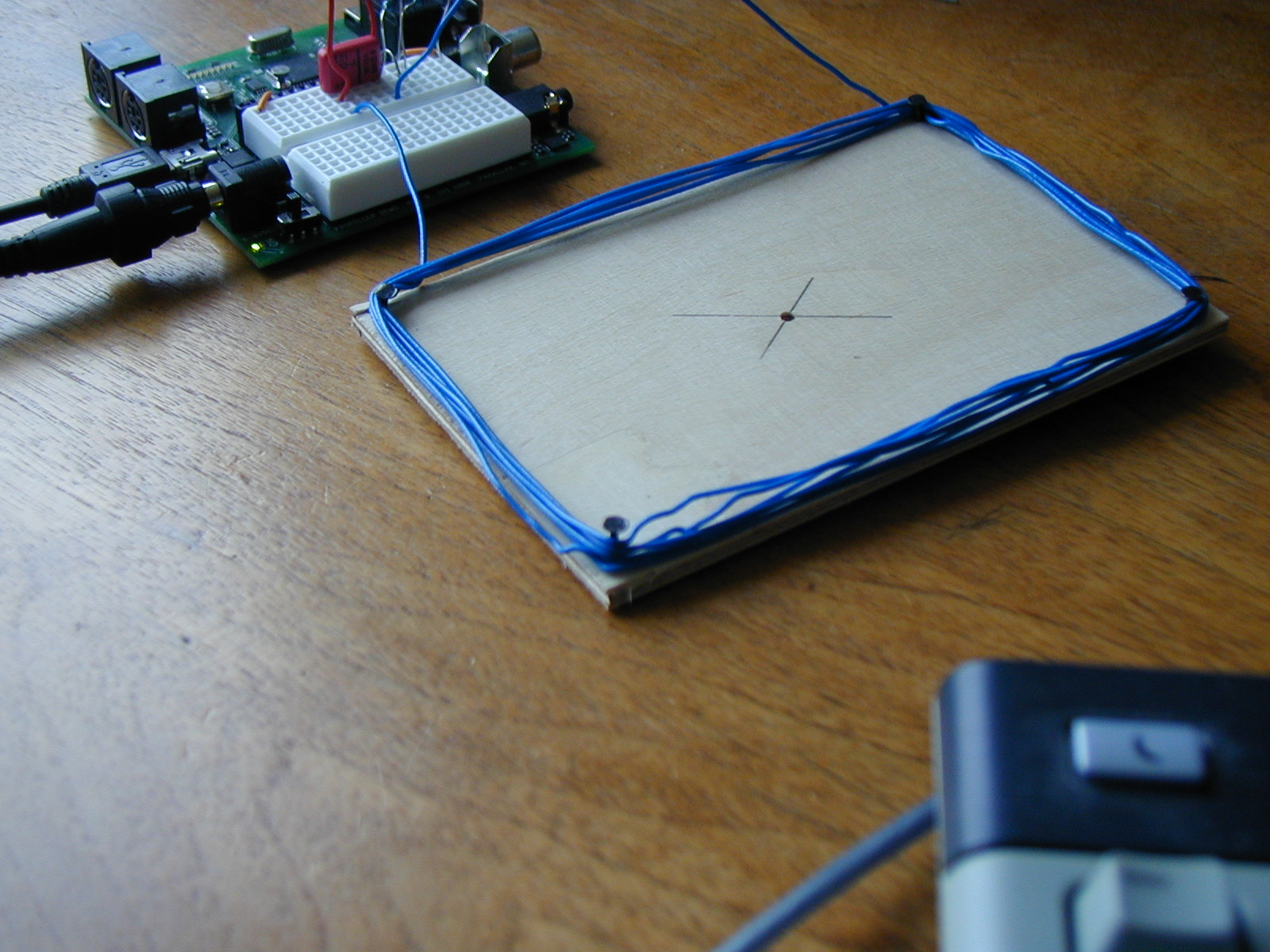
The picture shows the coil which has 6 turns.
Best luck for your experiments! Christof

some weeks ago my wife found a small older coin. Not a real treasure, but if you had that luck AND a propeller based metall detector you could find..... , whow!
At least if you look at the homepages of the sellers of metall detectors there are VERY impressive stories.....
So I startet to experiment with the metall detector from the Education Kit and you can find some code to find/track the center frequency below.
Many thanks for the Education Kit Lab, this is very interesting! I think the mixture of theory and doing ist top!
My question is now: What is the method to avoid to dig all these old nails?
My wedding ring gives some frequency shift up and high-frquency coil-kernel gives a shift down, but why? A steel bolt seems to shift the frequency up a little bit.
Are there ideas to find the depth and the estimated weight of this gold pot waiting for the prop- rogrammers?
About the program:
From Parallax Inc. Propeller Education Kit - Counters & Circuits Lab
CalibrateMetalDetector.spin
This modified version finds the resonant frequency automatically.
With "F" the minimum is looked for by gradual approximation.
With "C" the minimum is found through statistical evaluation:
First by the points on the right of and on the left of the minimum two straight lines are put with linear regression.
Their intersection is the center frequency.
With center frequency approx. 160kHz the standard deviation of the "F" method is 22Hz.
With "C" method it is 15 cycles per second.
In each case the search window must be determined first by hand.
A super-simple diagram shows the shift of the frequency on the terminal.
A coin in distance of about 60mm is detectable.
The picture shows the coil which has 6 turns.
Best luck for your experiments! Christof

1600 x 1200 - 391K
Comments
First let me say congratulations for taking and modifying the code to fit your needs.
Many people are frightened off at the thought of winding there own coils.· The circuit in the Propeller Lab Kit demonstrates a novel approach of using a 3 inch piece of hookup wire already included in the kit as a functional coil for detecting metal that minimizes the threat of winding any coils.
There are several methods for detecting metal and it depends on what you are essentially after.· Most metal detectors on the market today are PI (Pulse Induction) or BFO (Beat Frequency Oscillator) or some hybrid of the two.
PI works by sending a large magnetic burst of energy from a transmitting coil as a "PING".· Receiving coils then listen for the "PING" and note things such as Delay and Amplitude of the received signal.
BFO uses two coils, one located near the receiver head, and another located in the Metal detector BOX itself.· The idea is to have both coils oscillating at the SAME resonate frequency, by introducing metal to the receiver head you alter the resonate frequency resulting in an audible Beat frequency that can be heard... classic "click" or "chirp"
A "Hybrid" - usually in the form of the classic "D" head metal detector uses a center tapped coil as the transmitter/oscillator coil.· The RX coil is partially over the TX coil and partially off of the TX coil, so that the output of the RX coil is a null value.· Any metallic· disturbance inside the "eye" where the RX coil and the TX coil converge creates an Amplitude proportional to the imbalance on the RX coil.· It works on the RX coil outside of the "eye" also, but not nearly as sensitive.
See this link for an example of a "Hybrid" metal detector approach.
http://forums.parallax.com/showthread.php?p=467144
As far as type of metal... you've got me.· I'm not sure other than controlling the specific TX frequency and doing a frequency sweep.· The behavior of the RX response should show slight variations depending on the Depth, type of metal, and size of metal.· <--- This is up for experimentation.
·
·
▔▔▔▔▔▔▔▔▔▔▔▔▔▔▔▔▔▔▔▔▔▔▔▔
Beau Schwabe
IC Layout Engineer
Parallax, Inc.
Post Edited (Beau Schwabe (Parallax)) : 7/19/2007 8:41:28 PM GMT
I think that these modules can easily measure with milli-gauss resolution, with the earth's field at ~0.5 gauss.
Cheers!
Perhaps the following link is interesting for others looking for schematics. There are descriptions of coils there too.
http://geotech.thunting.com/cgi-bin/pages/common/index.pl?page=metdet&file=projects.dat
I am still thinking how to reduce the noise to be able to detect smaller frequency shifts.
Christof
·
"I am still thinking how to reduce the noise to be able to detect smaller frequency shifts."
·
Another "Hybrid" version, is to use a Beat frequency against the resonate frequency and use a High-Pass filter rather than the Low-Pass audible approach.
·
For example, say that your resonate frequency was 100kHz ... introduce a Beat frequency of 355kHz.·· Why 355kHz? because you will generate a sum frequency of 455kHz which they already make nice off-the-shelf High-Q filters for that are used in radio equipment at this particular frequency.· In this case, the absence of a 455kHz signal would indicate the presence of metal.· You could reverse this by offsetting your Beat frequency so that it "comes into range" of 455kHz, this way the presence of 455kHz would indicate the presence of metal.· Sweeping the Beat frequency and looking for 455kHz would be a way to detect the presence of metal also.
·
▔▔▔▔▔▔▔▔▔▔▔▔▔▔▔▔▔▔▔▔▔▔▔▔
Beau Schwabe
IC Layout Engineer
Parallax, Inc.
"Many people are frightened off at the thought of winding there own coils."
Today I nearly got crazy because I opened a new plastic bag with 115m of 0.2 diameter copper wire. This was not on a core but yust a coil of metal wire and it was immediately completly entangled....... Perhaps this is the reason.
Hello Beau and Paul again,
I am still fascinated with the possibilities of the super small circuit of Edu-Kit, so I have not thought of other sensors....
Now I have read a little bit in the patents in the link, I had mentioned.
One possibility to discriminate between ferrous and non ferrous metal is to use low frequency of about 16kHz or even less.
Then there is a shift up for nonferrous and down for steel and this works. Coil 8cm*12cm has now 30 windings, C=0,22µF.
A 2Euro coin in distance of 44mm in the center of the coil gives a frquency-shift from 17528 to 17530Hz. A bolt M8*40, lying, gives about 17526Hz.
At distance 18mm 17536Hz with the coin.
I was able to optimize the standard deviation to less than 1Hz: Search frequ window, freq step width, longer measurement.
I am amazed, what is possible with two resistors, one capacitor and a coil + Prop. + Software
But about 45mm seem to be the limit for objects of the mentioned size.
Does anyone know the limit for other frequ-shift detectors?
Beau, I do not have a 455kHz resonator in my crates but I have a 32768Hz cristal, perhaps I will try to experiment with this and your idea.
Christof
·
The crystal is not going to work, you need to filter the frequency.
·
You basically want a heterodyne receiver, but instead of detecting radio, your input frequency is from a resonating metal detector coil.
The attached schematic is a rough draft of what it might look like...
·
1) The 'input frequency' is basically what is coming from the resonate coil in the form of a sine wave.
2) The 'local oscillator' is what you sweep or tune so that it is 455kHz above or below the resonate frequency of the coil.
3) Both mixers in this case could simply be a resistor voltage divider.... output is the center tap.
4) The 'filter' basically blocks everything except 455kHz
5) The output should be amplified through an LM386 or something comparable.
·
Note: 1) Input frequencies to both of the mixers should be sine waves. (square or triangle might work??)
··· ····· 2) The Low-Pass optional filter will help to keep 1st, 2nd, and 3rd order harmonics out of the mixer
▔▔▔▔▔▔▔▔▔▔▔▔▔▔▔▔▔▔▔▔▔▔▔▔
Beau Schwabe
IC Layout Engineer
Parallax, Inc.
thanks for the input. I have now needed some time to make the next improvement, which is a little different to your suggestions....
Christof
http://forums.parallax.com/forums/default.aspx?f=21&m=206239
Wundervoll!!!
I haven't tried your circuit yet... but it is definitely on my list.
I would think that due to the geomagnetic field, the conduction electrons on the surface of the gold would be polarized differently than iron. So the resonant effect would show an angular dependence, which might or might not be strong enough to identify the difference between the two metals.
Rich
▔▔▔▔▔▔▔▔▔▔▔▔▔▔▔▔▔▔▔▔▔▔▔▔
Respectfully,
Jay K. Jeffries
Anyhow, a Flux Gate is a very sensitive magnetic field sensor of a very simple construction. One (sometimes two) piece of soft iron plus a couple of coils. Feed it with a frequency and evaluate the resulting AC signal. Ideal for the Prop and its counters. And probably useful for discriminating between ferrous and non-ferrous metals.
▔▔▔▔▔▔▔▔▔▔▔▔▔▔▔▔▔▔▔▔▔▔▔▔
But you could be suggesting we add a nail and a couple loops to the above sample, maybe?
Post Edited (Fred Hawkins) : 8/5/2007 9:41:26 PM GMT
The example is from the Counters lab v.8? for the Propeller Education Kit... http://forums.parallax.com/forums/default.aspx?f=25&m=189220&g=197397#m197397
Rich
Bitte entschuldigen Sie mein Deutsch. Mein Vater hat einen deutschen Namen. Aber meine Mutter war polnisch, Iren und Franz
sorry, the circuit should be visible in the link:
http://forums.parallax.com/forums/default.aspx?f=21&m=206239
(completed projects), there you find a document oszill2.doc.
Best luck!
Christof
It is... but I was looking at it on a Mac with Textedit...and of course it looked an empty file.
Thanks
Rich