

Timing a Square Wave output
 gtslabs
Posts: 40
gtslabs
Posts: 40
I am attempting to generate a Square Wave output for my Stepper motor with a range of 0.1 Hz to 2000 Hz
I dont have a SX chip yet so I used the simulator to test the accuracy of the output.
I made a table of the cycles executed in the loop:

What kind of accuracy can I expect with the real chip? Is there a better way to do this?
I looked at the FREQ command but I am running this output 24 hour -7 days at times.
Also how much will temperature effect my timing? It will be housed near the driver and motor in an enclosure.
Thanks
Steve
I dont have a SX chip yet so I used the simulator to test the accuracy of the output.
DEVICE          SX28, OSC4MHZ, STACKX, OPTIONX
FREQ            4_000_000
ID  "TOGGLE"

SquareWavePin VAR RB.0 ' Pin used for SQ output

'Need eventual 24bit shiftin or serin of new HalfPeriod value based on interrupt of an input pin state.

'HalfPeriod Var Word
'HalfPeriod = 5000  (This line does not work  if I use it in place of the next one)

HalfPeriod con 5000


PROGRAM Start

Start:


output SquareWavePin


  DO
  SquareWavePin = ~ SquareWavePin
  PAUSEUS HalfPeriod
  LOOP
I made a table of the cycles executed in the loop:
What kind of accuracy can I expect with the real chip? Is there a better way to do this?
I looked at the FREQ command but I am running this output 24 hour -7 days at times.
Also how much will temperature effect my timing? It will be housed near the driver and motor in an enclosure.
Thanks
Steve
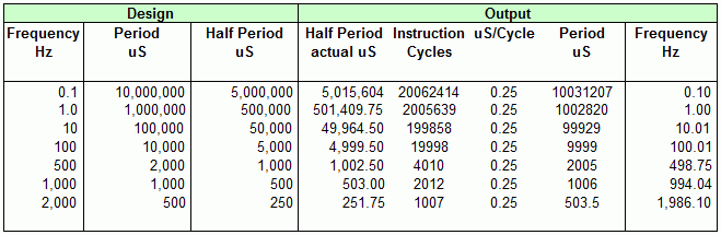
659 x 215 - 10K
Comments
Most likely. There is almost always a better way of doing something!
The trick will be to count your clock cycles very carefully. If you can do this well you should be able to achieve your desired frequency to within a few clock cycles. If you were desiring a few fixed frequencies this would be feasible. With the range you desire I am not sure this is realistic. I would not want to try it myself.
You may be able to achieve very good results with the built in timers in an SX48. You should seriously consider those before ruling them out.
The FREQ command is designed as a one time adjustment to be used at compile time to account for the cycles that are lost in an interrupt service routine. If you to not have interrupts enabled the FREQ setting should match the frequency of your clock source.
If you use a precision external clock source the temperature effect should be minimal and known. If the temperature is held constant you can probably adjust for its effect.
I expect there are others with more experience than I have who can provide additional insights.
- Sparks
I had to add some code to inc a counter and make the pause a variable.
Making it a variable made it outside of my tolerances using the Pauseus statement.
I switched to the Pause statement and it is much more accurate. The problem is I need to have a duration of 5.7 ms for example.
I know the pause allows a decimal but I am using a variable which wont accept the decimal.
I really need accurate outputs from 100 hz to 0.1 hz by 0.1 hz
I have another application that needs 2000 hz by 1% error
And a fast return rate somewhere around 5,000 hz where accuracy is not important.
I am thinking of using some branch to use the higher speed. I assume I can get 2-5 KHz using the PWM?
I will be using an externasl oscillator.