

ISD4004 Sound Chip Controller

First, I want to thank everyone who helped with this project when I ran into problems. Bean and Jonny Mac are two that spring into my head at the moment, but there were others.
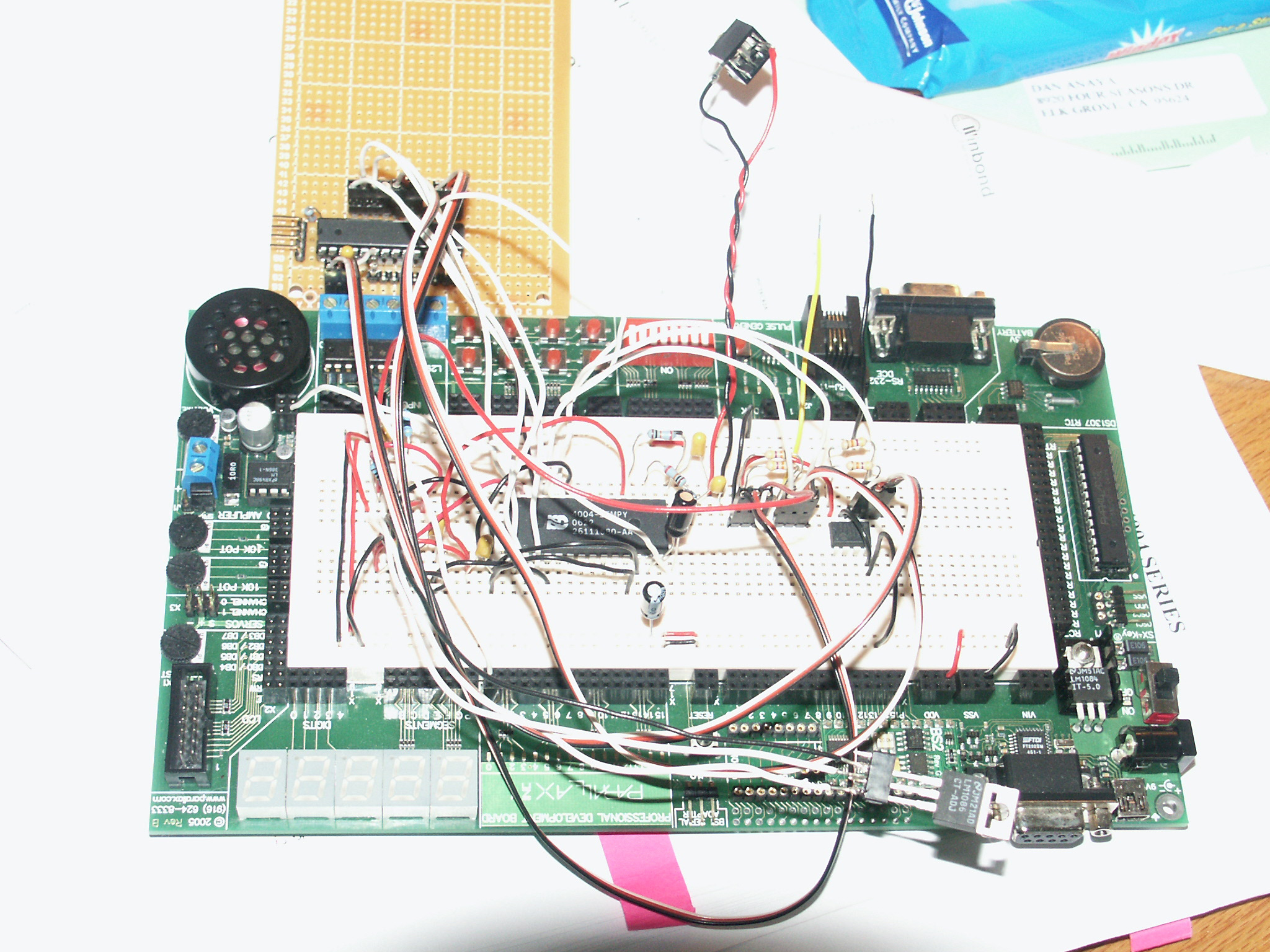
Although I don't have·the PCB·made yet, it's ready to go. I know if I keep waiting, I'll never post the project.
Several interesting problems had to be solved while working on this project, and I hope the solutions I came up with help others working on similar projects or who may want to use parts of this project.
Purpose of the Project:
To make a controller for the ISD4004·analog sound chip.
[noparse][[/noparse]This chip records sounds in analog...not digital. Has decent sound quality, and records for 16 minutes. You can play back sounds of any length, and you can use it to string together words to make a sentence.]
The controller has to allow me to record sounds and play them back by sound number.
[noparse][[/noparse]To accomplish this, I created a library of procedures to controll all of the functions of the chip. In addition, the index of sounds has to be saved so I can play back the sounds without having to rebuild the index.]
The controller must use SPI to talk to the sound chip(ISD4004-16M), and I2C·to talk to the EEPROM (24LC16B 16K memory) that stores the location of each sound.
Difficulties Encountered on the Project:
-The project runs at 3 volts -This causes a problem programming the SX-28 and requires·the SX·Key Ring to program and debug at low voltage.
-One chip uses the SPI protocol: ISD4004-16M
-One chip uses I2C the protocol: 24LC16B 16K memory
-Poor documentation on exactly how the ISD4004 stores and retrieves sound.
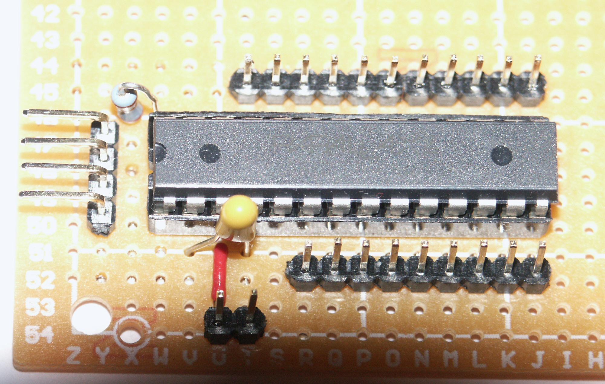
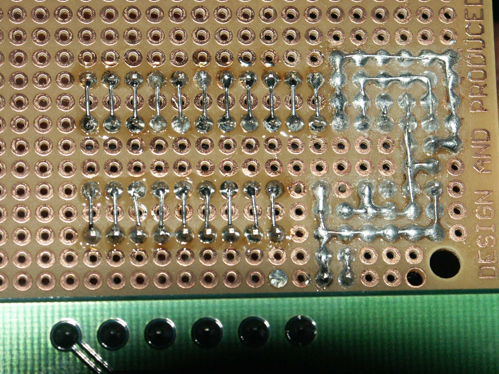
As a by product of the problems I ran into, I created a small SX Prototype board that others might find useful. When I tried to prototype (low voltage) with an SX chip on the Professional Development Board a problem with capacitance prevented me from debugging at all. You can check this thread for a detailed explaination of what happened:
http://forums.parallax.com/showthread.php?p=644066
The prototype board takes a jumper with what ever voltage you want to feed it - within the limits of the SX-28 chip.
Future Changes and Improvements:
This is the prototype project I used as a proof of concept. The actual sound board programming will change a little and will watch a wireless module for information on what sound to play. The wireless module will communicate using a single wire.
-An amplifier module will plug into this board-[noparse][[/noparse]Separate project-In progress]
-A wireless module will plug into this board-[noparse][[/noparse]Separate Project -Completed]
-A USB interface to IBM·PC will plug into the board to allow recording from a laptop computer. [noparse][[/noparse]Separate project]
-A Record button will be added to the PCB- It actually exists in the code and in the prototype [noparse][[/noparse]Enhancement]
-An Erase All button will be added-Currently, in the code, if you push the STOP button when you turn it on, it will erase all sounds. [noparse][[/noparse]Enhancement]
-A Play Next Sound button will be added-To review sounds on the chip. [noparse][[/noparse]Enhancement]
-You can use the RAC (row address clock) for servo timing if you are doing animatronics, or use it to know when to load the next sound when you are building·a sentence. More information can be found in this document:
http://www.winbond-usa.com/products/isd_products/chipcorder/applicationbriefs/an_7.pdf
More information on the ISD4004 can be found at:
http://www.winbond-usa.com/en/content/view/156/1565/
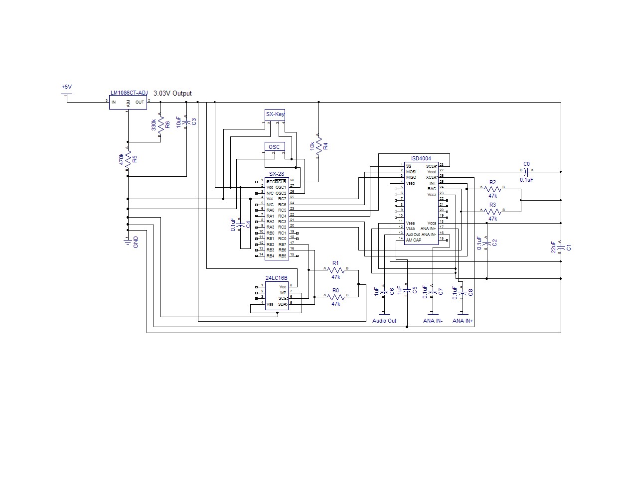
A special thanks to Parallax for making such an awesome PDB and such great products!! My appologies on the schematic...I need to learn how to do a better job making one. Thankfully the PCB software has autorouting...hehe.
UPDATES:
I made a mistake in attaching RB.7 and RB.6. RB.7 should be attached to the SCL, not SDA. RB.6 should be connected to SDA.
I uploaded a better view of the schematic. The software doesn't do a good job of producing a clear JPG file. If you zoom it to 150%, you should be able to read it.
Dan
Post Edited (DosManDan) : 7/29/2007 5:52:51 AM GMT
Although I don't have·the PCB·made yet, it's ready to go. I know if I keep waiting, I'll never post the project.
Several interesting problems had to be solved while working on this project, and I hope the solutions I came up with help others working on similar projects or who may want to use parts of this project.
Purpose of the Project:
To make a controller for the ISD4004·analog sound chip.
[noparse][[/noparse]This chip records sounds in analog...not digital. Has decent sound quality, and records for 16 minutes. You can play back sounds of any length, and you can use it to string together words to make a sentence.]
The controller has to allow me to record sounds and play them back by sound number.
[noparse][[/noparse]To accomplish this, I created a library of procedures to controll all of the functions of the chip. In addition, the index of sounds has to be saved so I can play back the sounds without having to rebuild the index.]
The controller must use SPI to talk to the sound chip(ISD4004-16M), and I2C·to talk to the EEPROM (24LC16B 16K memory) that stores the location of each sound.
Difficulties Encountered on the Project:
-The project runs at 3 volts -This causes a problem programming the SX-28 and requires·the SX·Key Ring to program and debug at low voltage.
-One chip uses the SPI protocol: ISD4004-16M
-One chip uses I2C the protocol: 24LC16B 16K memory
-Poor documentation on exactly how the ISD4004 stores and retrieves sound.
As a by product of the problems I ran into, I created a small SX Prototype board that others might find useful. When I tried to prototype (low voltage) with an SX chip on the Professional Development Board a problem with capacitance prevented me from debugging at all. You can check this thread for a detailed explaination of what happened:
http://forums.parallax.com/showthread.php?p=644066
The prototype board takes a jumper with what ever voltage you want to feed it - within the limits of the SX-28 chip.
Future Changes and Improvements:
This is the prototype project I used as a proof of concept. The actual sound board programming will change a little and will watch a wireless module for information on what sound to play. The wireless module will communicate using a single wire.
-An amplifier module will plug into this board-[noparse][[/noparse]Separate project-In progress]
-A wireless module will plug into this board-[noparse][[/noparse]Separate Project -Completed]
-A USB interface to IBM·PC will plug into the board to allow recording from a laptop computer. [noparse][[/noparse]Separate project]
-A Record button will be added to the PCB- It actually exists in the code and in the prototype [noparse][[/noparse]Enhancement]
-An Erase All button will be added-Currently, in the code, if you push the STOP button when you turn it on, it will erase all sounds. [noparse][[/noparse]Enhancement]
-A Play Next Sound button will be added-To review sounds on the chip. [noparse][[/noparse]Enhancement]
-You can use the RAC (row address clock) for servo timing if you are doing animatronics, or use it to know when to load the next sound when you are building·a sentence. More information can be found in this document:
http://www.winbond-usa.com/products/isd_products/chipcorder/applicationbriefs/an_7.pdf
More information on the ISD4004 can be found at:
http://www.winbond-usa.com/en/content/view/156/1565/
A special thanks to Parallax for making such an awesome PDB and such great products!! My appologies on the schematic...I need to learn how to do a better job making one. Thankfully the PCB software has autorouting...hehe.
UPDATES:
I made a mistake in attaching RB.7 and RB.6. RB.7 should be attached to the SCL, not SDA. RB.6 should be connected to SDA.
I uploaded a better view of the schematic. The software doesn't do a good job of producing a clear JPG file. If you zoom it to 150%, you should be able to read it.
Dan
Post Edited (DosManDan) : 7/29/2007 5:52:51 AM GMT

2048 x 1536 - 864K
2001 x 1272 - 861K
2048 x 1536 - 420K
1256 x 970 - 107K
Comments
Nice Application. Too bad the isd4004 chip is so expensive.
Bean.
▔▔▔▔▔▔▔▔▔▔▔▔▔▔▔▔▔▔▔▔▔▔▔▔
“The United States is a nation of laws -· poorly written and randomly enforced.” - Frank Zappa
- - - - - - - - - - - - - - - - - - - - - - - - - - - - - - -
www.hittconsulting.com
·
The total cost of the controller was about:
ISD4004· $12.90
24LC16B· $00.90
SX-28···· $02.51
Other····· $03.50
Total······ $19.81
I bought a few sound boards that only did 2 mins of sound and paid about $49 each, so I thought this was a pretty good deal for 16 mins.
Another option was to buy the Quadravox QV606M1. Althought the sound quality of mine isn't as good as the Quadravox QV606(it has near CD sound quality,·14 mins, and costs $57) my solution was less expensive.
As the MasterCard commercial says....cost of sound board $19....the cost of saying I did it....priceless...hehe
Smile!
Dan
·
Who has a C example to control ISD4004 16m via SPI
I'm wondering is it practical to use a pic chip with the isd4004 instead of the sx28, or is this the best microcontroller you think is suitable for this project?
And also how did you record the audio, was it through a microphone or was digitally through the pc?
Finally what is the purpose of the 24LC16B, is this for the amplification?
Thanks
I'm sure you could use a PIC chip with the ISD4004. I happen to use Parallax products and the SX-28 was the best solution for the product.
The recording could be made by a PC or other device. Some of the ISD4004 documentation has instructions for building an AGC (automatic gain control) microphone circuit. But, I just connected an earphone jack to my MP3 and connected the other end to the ISD4004 and hit record on the board and Play on the MP3.
Good question about the 24LC16B. I don't think anyone else noticed it!
The first word of the memory chip held the number of sounds that were recorded. The second word stored the location where the next sound address was to be saved. Basically, the memory chip acted as an index to where the sounds are stored on the ISD4004.
Here is the breakdown:
24LC16B Memory locations - sound index - By Word Location:
Word 1: How many sounds are stored on the ISD4004
Word 2: Where is the next 24LC16B memory location to store the sound address from the ISD4004
Word 3..+: Each word from here on is the address where a sound was stored on the ISD chip
For example, if I had 3 sounds stored on the ISD at memory locations 1000, 2000, 3000 here is what would be stored on the 24LC16B in Hex. Remember, the next location where a sound address would be stored would be 10 (0Ah):
0003·000A 03E8 07D0 0BB8
Since each sound memory location takes up a Word (2 bytes) the next memory location is always stored two bytes past the last index location. In this case, the data in byte 9 is·B8 (remember to start from zero, not one). The next address would be stored after this, starting with byte 10 (where the ???? appear below).
0003·000A 03E8 07D0 0BB8 ????
For an amplifier you would want to use something like an LM386 (low power) to something with a little more power.
Hope this helps,
Dan
This forum is not a good place to look for C code or code for microcontrollers other than those made by Parallax. The Basic Stamps are only programmed in Basic. The SX is programmed either in assembly or in Basic (SX/B), and the Propeller is programmed mostly in Spin and some assembly language. There is a new 3rd party C compiler available for the Propeller, but it's quite new and there are very few I/O drivers available yet in C.
▔▔▔▔▔▔▔▔▔▔▔▔▔▔▔▔▔▔▔▔▔▔▔▔
When the going gets weird, the weird turn pro. -- HST
1uffakind.com/robots/povBitMapBuilder.php
1uffakind.com/robots/resistorLadder.php
I'm working on a similar project however I haven't been able to get the interrupt working in my code. I am trying to place an EOM marker after recording is stopped, but I haven't been able to figure it out. I noticed you omitted this part from your code, I am curious if you ended up using this command for your project and how you were able to do it? Any help would be great...
Thanks
Post Edited (beats) : 11/16/2008 8:28:20 PM GMT
If you try out my code, you will find it saves the sounds and plays them back perfectly. You simply need to tell it the number of the sound you want to play. It will find it and play the sound, stopping at the end of the sound.
I'll check and see if there was a way to place the EOM marker, I've forgotten since it has been a while since I read the specs.
Dan
But what do you mean you need to tell it the sound number to play? how would you "tell it," is it supposed to prompt you on the screen?
Also, if you dont mind, but I couldn't help but notice this snippet of code in your program:
doesn't this cause an endless loop in the program?
Play_Sound_Number
To use it, pass the number of the sound you want to play
Play_Sound_Number 5
In the: Wait_For_Stop
routine, it is recording a sound and waiting for you to press the Stop button. The two IF statements act as a key debounce routine. This avoids the code reading a start/stop press while you are pushing the button one time. Once it detects you pressing the button, it loops until you release the buttton.
In the: Wait_Sound
routine, it is waiting for the ISD to signal the sound is finished playing. It does this by raising the INT line (puts power on it). This allows you to detect when the chip is busy and avoid sending commands to the ISD while it is already playing a sound.
Dan
Erase_Sounds
Before you attempt to record to the chip. This sets up the starting addresses in the EEPROM chip. After that, you can record away, then play them back by number.
Dan