

SpinStudio almost ready
 parts-man73
Posts: 830
parts-man73
Posts: 830
With the recent trend of announcements of boards available. I thought I'd share the latest news about SpinStudio.
Some of you may remember that back in December I shared a peek at my design for a new development system named SpinStudio. I asked for some volunteer beta-testers. I have since made several design changes, and I am about ready to start selling them.
Last week I released part of the package, with can also be used with other development systems, the SD card adapter. That was an instant success that went on backorder within a few hours. (I'm expecting a shipment that will fill all the backorders and then some, later this week)
A quick description of this design.
There is a mainboard. This consists of
The following peripheral boards are finished, and will be available when I officially launch this product.
Other peripheral boards are planned but not completed. A blank board is definitely going to be made, for users to make their own designs that can simply be plugged in / swapped as needed. Each peripheral socket includes connections for 8 Propeller I/O lines, 3.3V, 5V, Ground, SDA and SCL for I2c bus.
Sockets A-D provide access to the following I/O lines - Socket A (p0-p7), Socket B (p8-p15), Socket C (p16-p23) and Socket D (p24-p27) Pins p28-p31 are reserved for I2c bus and programming.
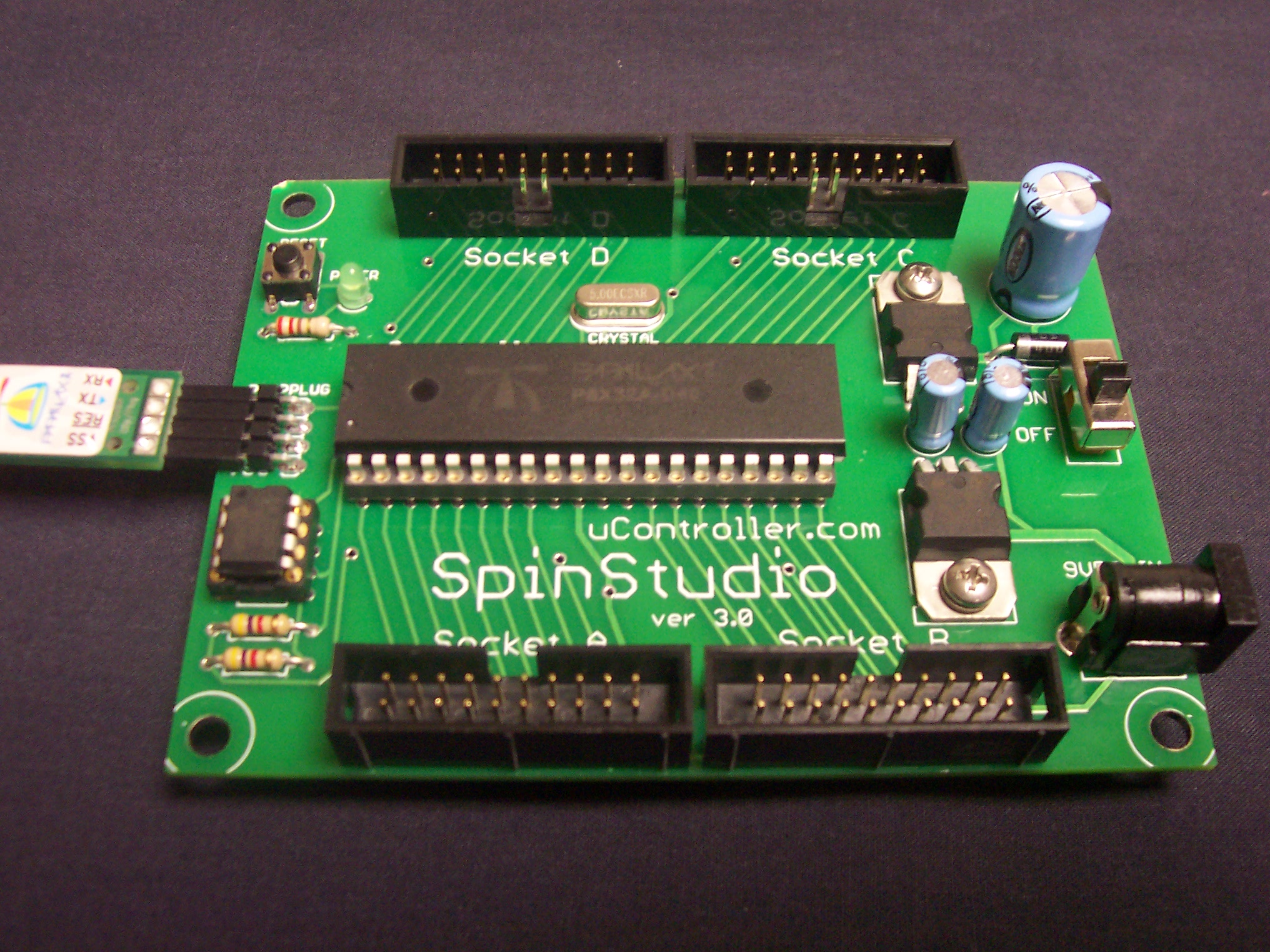
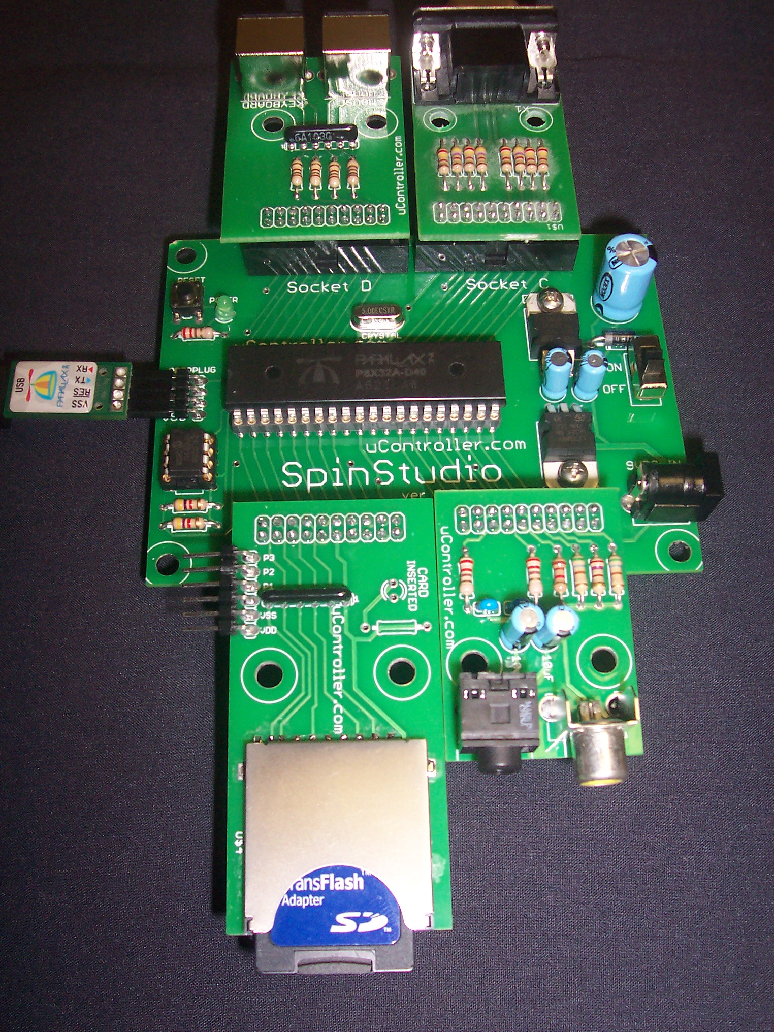
I've attached pictures of the mainboard alone, and the Mainboard with 4 peripheral boards plugged in.
These are going to be sold in kit form, so soldering will be required. I purposely used all through-hole parts for this reason. The one exception is the SD card socket, which is surface mount. I will be soldering this part to the circuit board before sending those.
The circuit boards are in and ready, just waiting for a shipment of parts to come in to complete the kits. I also want to fill all the SD card adapter backorders before starting a new product.
▔▔▔▔▔▔▔▔▔▔▔▔▔▔▔▔▔▔▔▔▔▔▔▔
Brian Meade
"They who dream by day are cognizant of many things which escape those who dream only by night" - Edgar Poe
Some of you may remember that back in December I shared a peek at my design for a new development system named SpinStudio. I asked for some volunteer beta-testers. I have since made several design changes, and I am about ready to start selling them.
Last week I released part of the package, with can also be used with other development systems, the SD card adapter. That was an instant success that went on backorder within a few hours. (I'm expecting a shipment that will fill all the backorders and then some, later this week)
A quick description of this design.
There is a mainboard. This consists of
- A socket for a DIP propeller and EEPROM
- 5 volt and 3.3 volt regulators
- neccessary pullup resistors, power filtering/bypass capacitors, reset button, power switch and power indicator LED
- 4 pin right angle programming header, for the connection of a PropPlug
- 4 connectors for peripheral boards
The following peripheral boards are finished, and will be available when I officially launch this product.
- Keyboard/mouse
- VGA
- Composite Video/Stereo Audio (sound is not amplified)
- Parallel LCD adapter (for a Hitachi HD44780 type LCD)
- General I/O adapter, provides direct access to I/O pins, also has servo type connections with appropriate power rails and current limiting resistors
- and of course....the already released SD card adapter
Other peripheral boards are planned but not completed. A blank board is definitely going to be made, for users to make their own designs that can simply be plugged in / swapped as needed. Each peripheral socket includes connections for 8 Propeller I/O lines, 3.3V, 5V, Ground, SDA and SCL for I2c bus.
Sockets A-D provide access to the following I/O lines - Socket A (p0-p7), Socket B (p8-p15), Socket C (p16-p23) and Socket D (p24-p27) Pins p28-p31 are reserved for I2c bus and programming.
I've attached pictures of the mainboard alone, and the Mainboard with 4 peripheral boards plugged in.
These are going to be sold in kit form, so soldering will be required. I purposely used all through-hole parts for this reason. The one exception is the SD card socket, which is surface mount. I will be soldering this part to the circuit board before sending those.
The circuit boards are in and ready, just waiting for a shipment of parts to come in to complete the kits. I also want to fill all the SD card adapter backorders before starting a new product.
▔▔▔▔▔▔▔▔▔▔▔▔▔▔▔▔▔▔▔▔▔▔▔▔
Brian Meade
"They who dream by day are cognizant of many things which escape those who dream only by night" - Edgar Poe
2032 x 1524 - 840K
1524 x 2032 - 1M
Comments
I really enjoyed building my serial PropStick kit. This looks like a nice one to build too.
Looking at the SpinStudio board I think its simplicity is the best part - it leaves your options open for how you want to use it. For instance, you designed the pin headers to be expansion slots, but they would also allow one to easily incorporate the SpinStudio into a project by connecting ribbon cables to the four ports.
That's exactly what I had in mind. I also had future Propellers in mind also, if a Propeller with more outputs is released, I can simply create a different mainboard with more sockets.
The peripheral boards have a female 20 pin double row header mounted to the bottom, so they install on the mainboard by pressing that header down into the socket on the mainboard. But you could just as easily substitute a shrouded male header, and use a ribbon cable to connect them.
And designing future peripherals... you can simply plug a new design into your existing mainboard! And with the blank peripheral board, you can design your own!
The pinout for the peripheral sockets will be included in the documentation, I do encourage others to offer there own peripheral devices for the SpinStudio mainboard.
One other fact that I forgot to mention. The size of the mainboard is identical to the Protoboard and Board of Education. So it can be mounted to a Boe-Bot chassis. The peripheral board can be connected with ribbon cables, etc I think you get the idea.
That also was the idea. Most potential customers enjoy soldering and will feel more vested in the product, if they had a part in building it. With all through hole parts, you can easily probe points with a multi-meter or O-Scope if you wanted.
I've set the prices at...
- Mainboard - $29.99
- Keyboard/Mouse - $11.99
- VGA - $11.99
- Parallel LCD - $11.99
- I/O and Servo - $11.99
- Audio/Composite video - $11.99
- SD Card adapter - $17.50
▔▔▔▔▔▔▔▔▔▔▔▔▔▔▔▔▔▔▔▔▔▔▔▔Brian Meade
"They who dream by day are cognizant of many things which escape those who dream only by night" - Edgar Poe
Nice idea ... Just wondering about regulator caps. Vin to gnd .. or are they under the main board ?
Do you have pics of bottom copper layer (ref Ground Planing)? Can't see from the image but does (P16) pin 20 of prop run under the tab of the regulator on its way to 'Socket C'.
Regards,
Quattro
▔▔▔▔▔▔▔▔▔▔▔▔▔▔▔▔▔▔▔▔▔▔▔▔
'Necessity is the mother of invention'
Post Edited (QuattroRS4) : 7/4/2007 8:27:33 PM GMT
As far as power supply capacitors, there is a 1000 uF capacitor on the input. A 10 uf cap on the output of the 5 volt regulator, which in turn feeds the 3.3 volt regulator, then another 10 uF cap on the output of the 3.3 V regulator.
I'll do a screen capture later today from GerbV of the top and bottom layers. I don't have that program installed on my laptop that I'm using now.
btw...if you have different ideas for the regulator caps, it would be easy enough to substitute them. The 1000 uF in, 10 uF out I've used in many previous designs and not had a problem. The 5 volt regulator is a plain old 7805, the 3.3 Volt regulator is a ST Micro LF33ABV.
▔▔▔▔▔▔▔▔▔▔▔▔▔▔▔▔▔▔▔▔▔▔▔▔
Brian Meade
"They who dream by day are cognizant of many things which escape those who dream only by night" - Edgar Poe
The idea is similar to the E-Blocks concept by Matrix Multimedia
http://www.matrixmultimedia.com/
and there seems to be a good market for that...
Regards,
QuattroRS4
▔▔▔▔▔▔▔▔▔▔▔▔▔▔▔▔▔▔▔▔▔▔▔▔
'Necessity is the mother of invention'
Post Edited (QuattroRS4) : 7/4/2007 8:51:01 PM GMT
One of the nice things about this design is the fact that there is no "dedicated" pins (except P28-P31, but even they can be used after boot with certain precautions)
For example, if you have a design that doesn't need VGA support, just unplug that module and plug in a general IO module, and you can use those 8 I/O pins.
If your design only requires composite video and audio, you have access to the other 3 sockets(24 IO's)
All of the other development platforms are rigid in their usage of IO pins, whereas my system is very flexible. In fact, it'd probably be possible to duplicate certain ports if the need ever arises. For example, you could plug in 3 VGA monitors and run all 3 off from 1 Propeller, as long as you have enough cogs to make it work. I thought about making a bouncing ball demo, where you would have 3 VGA screens side by side, and the ball will start on the leftmost screen, then when it left the right side of that screen, it would appear on the center screen, and so on.
▔▔▔▔▔▔▔▔▔▔▔▔▔▔▔▔▔▔▔▔▔▔▔▔
Brian Meade
"They who dream by day are cognizant of many things which escape those who dream only by night" - Edgar Poe
You mentioned that the main board is the same size as a BOE/Proto board, with all four peripheral slots ocupied on the main board, what overall foot print are we talking about. Since I have my iRobot Create project going now, I would like to get an as to how much space it would take up, and whether it would fit.
Ray
Yes, a Xbee adapter has been in the back of my mind. It won't be available at first, but it will be one of the first that I will roll out after the launch of SpinStudio. I think the current compliment of boards will suit most users, but as new things are done with the Propeller, Add-on peripheral boards can easily be designed and simply plugged in, unlike other development boards.
Future peripheral boards I have in mind right now (feel free to suggest others) are Xbee, Stepper motor driver and a motor controller.
With the peripherals plugged in as shown in the second picture in the first post of this message, the overall size is 4"x7". One suggestion thus-far has been to use a ribbon cable between the Mainboard and the peripheral boards, one other thought would be to use right angle headers when assembling the peripheral boards. Then they would stand straight up, that may help if you have more vertical clearance than horizontal.
▔▔▔▔▔▔▔▔▔▔▔▔▔▔▔▔▔▔▔▔▔▔▔▔
Brian Meade
"They who dream by day are cognizant of many things which escape those who dream only by night" - Edgar Poe
here is a link to a another members current work using that chip http://forums.parallax.com/showthread.php?p=622051
When do you think you will have these items available ?
Mainboard - $29.99
Keyboard/Mouse - $11.99
VGA - $11.99
Parallel LCD - $11.99
I/O and Servo - $11.99
Audio/Composite video - $11.99
Rob7
The supplier stated that they will have the parts in within 1-2 weeks, and I paid extra for express shipping. I am excited to get these done!
▔▔▔▔▔▔▔▔▔▔▔▔▔▔▔▔▔▔▔▔▔▔▔▔
Brian Meade
"They who dream by day are cognizant of many things which escape those who dream only by night" - Edgar Poe
Can't wait to order and play !
Rob7