Calibrating the Boe-Bot my way.
Hello...
I'm pretty much done with the boe-bot handbook. All throughout the book I was left with a bitter taste after the calibration part. To me, using the straight line method wasn't enough. It wasn't as precise as I wanted, and then if I wanted to work out different speeds, I'd have to do the straight line method for each different setting. For example: if I wanted to run at half speed, 1/4 speed, etc, I would have to work out each setting with the straight line method. For those that don't know, basically the straight line method is playing with different pulses on the servos until the bot travels in a straight line, indicating that both servos are calibrated. No offense to Parallax at all, but this just wasn't enough for me. Not having an encoder, I just used the same principle as the RPMs activity, but a bit more automated.
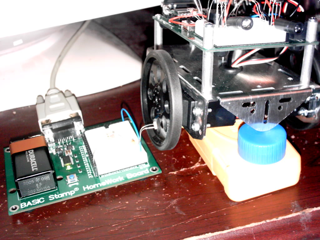
I set up a RC photoresistor circuit the following way: picture 1.
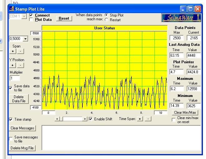
Now look at picture 2.
Basically, each time the photoresistor hits one of the openings on the boe-bot wheels, there's a spike on graph. From here on you can get a bit more precise RPM count.
Code wise, I plan on taking the highest value where all spikes are above of (on the graph it'd be about 4380) and setting that as a threshold. Then using a counter to tell how many spikes occur in X number of seconds. The threshold will be used as the value where anything above that will be considered a spike. By having the RPMs update on the screen, I can get better numbers as to what pulse I need to set each servo to in order to get the RPMs I want. If I want to work out the RPMs needed for 1/2 full speed, I can just pick a pulse and go from there. Also, I can even have two circuits running on each wheel and have the program adjust one of the servo's pulse to match the other.
I didn't put this in completed projects because I don't really consider it such... just me being picky and anal about my results.


Comments
If you are powering your servos from unregulated batteries, there will be significant drift in your
results as the batteries age. I would also expect drift over time as the gears wear. But
certainly, automating the calibration will always be a win. (I know, I just spent about an hour
calibrating a forward and a 180 degree turn---manually.)
If you do end up getting a fairly accurate pulse->speed curve, I'm sure we'd love to see it.
I've noticed some interesting things near the deadband on my servos. There are points near
the deadband where the servos will spin slowly but if you "stop" the servos manually, they
will stay stopped. So there appears to be some hysteresis or something going on in there that
is a bit tricky.
I'm also not certain how reproducible the speed curve will be; I can imagine situations where,
because of the particular orientation of the rotor, certain pulse widths would give different
speeds at different times.
Then there's the temperature effect; as the servo warms up, and the electronic circuitry in it
warms up, that's probably going to affect something too.
All in all, open-loop dead reckoning will probably always be something of a Smile shoot.