

MUST READ for PDB and BOE USB users: javelin usb troubleshooting
 Peter Verkaik
Posts: 3,956
Peter Verkaik
Posts: 3,956
I have received a Board of Education USB rev.C
http://www.parallax.com/detail.asp?product_id=28850
No problem installing drivers and the javelin gets recognized.
Provided schematic on the product page above:
http://www.parallax.com/dl/docs/prod/boards/BoeUSBrevB.pdf
Since I am doing the new javelin IDE beta, I want to resolve some
timing issues with usb connected javelins.
There are 2 known problems:
1) after downloading a very small program to the javelin, it no longer
accepts new downloads
2) it is not possible to receive input from the message window
I now start trying to resolve issue 2.
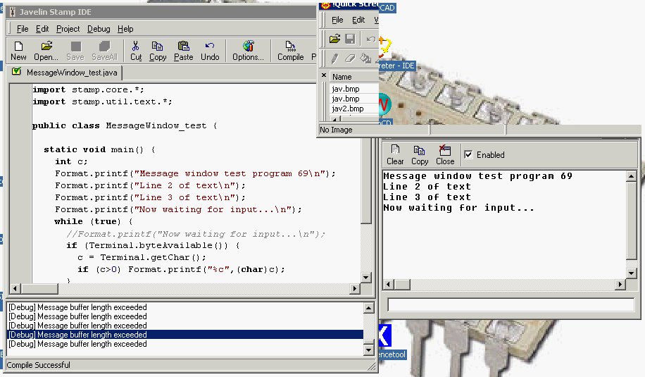
When I run a simple program that prints some lines and than requests
some input from the message window the trouble starts.
A continues flow of debug messages stating the message buffer length
has exceeded.
I noticed a red led on the board (next to label P1) that flashes every 8 seconds or so,
the led turns on for about 0.75 second, than dims for about 7.5 seconds.
The schematic from the link above, is for revision B and does not show
the leds.
Can someone post the schematic for revision C? These leds may be part of
the problem.
For those of you that also have problems with usb connected javelins,
please post any comment that may be useful.
regards peter
Post Edited By Moderator (Chris Savage (Parallax)) : 6/19/2007 6:30:41 PM GMT
http://www.parallax.com/detail.asp?product_id=28850
No problem installing drivers and the javelin gets recognized.
Provided schematic on the product page above:
http://www.parallax.com/dl/docs/prod/boards/BoeUSBrevB.pdf
Since I am doing the new javelin IDE beta, I want to resolve some
timing issues with usb connected javelins.
There are 2 known problems:
1) after downloading a very small program to the javelin, it no longer
accepts new downloads
2) it is not possible to receive input from the message window
I now start trying to resolve issue 2.
When I run a simple program that prints some lines and than requests
some input from the message window the trouble starts.
A continues flow of debug messages stating the message buffer length
has exceeded.
I noticed a red led on the board (next to label P1) that flashes every 8 seconds or so,
the led turns on for about 0.75 second, than dims for about 7.5 seconds.
The schematic from the link above, is for revision B and does not show
the leds.
Can someone post the schematic for revision C? These leds may be part of
the problem.
For those of you that also have problems with usb connected javelins,
please post any comment that may be useful.
regards peter
Post Edited By Moderator (Chris Savage (Parallax)) : 6/19/2007 6:30:41 PM GMT
916 x 535 - 114K
Comments
The only difference between the USB-BOE Rev B & C is we went from using the FT232BM to using the FT232R. The LEDs are actually connected to special pins on the FT232R that by default are RX/TX indicators…They’re not connected to the signal lines but are driven independently. I believe the Red is traffic to the PC (TX) and the Blue one is RX. The problems existed on the Rev B board as well. Nonetheless I will try to get you the schematic. Take care.
▔▔▔▔▔▔▔▔▔▔▔▔▔▔▔▔▔▔▔▔▔▔▔▔
Chris Savage
Parallax Tech Support
I was just trying out product #28030 (USB to 232 adapter) that uses the FT232RL
chip. This is the same as the FT232RQ on the BoE USB rev.C but in a different
package. The FT232RL does allow a javelin to receive input via the JIDE port,
whereas the FT232RQ does not. Both use the same VCP drivers.
I had partially success in receiving with the FT232RQ but it was very unstable.
(only 1 out of 20 characters or so was received correctly).
Since both chipsets program the javelin without trouble, they must both be
able to allow the javelin to receive data via the JIDE port.
I keep trying to make this work.
regards peter
I forgot to mention…The big difference between using the USB-BOE and using a Serial Board with our USB to 232 Adapter is this…The USB-BOE uses transistors to switch the signals levels (see the attached schematic I found, ignore the Rev) whereas the USB to 232 uses a MAX232 Line Driver. So while they’re using the same chip, the signals in between go through a different circuit. Generally the effect is the same, but on the Javelin there seems to be an issue with the transistor circuit via USB. I hope the schematic helps and/or makes this clearer for you. It is a difficult issue. Take care.
▔▔▔▔▔▔▔▔▔▔▔▔▔▔▔▔▔▔▔▔▔▔▔▔
Chris Savage
Parallax Tech Support
I think I cracked it.
You need to replace the current Terminal.java with the attached one.
Rename the current Terminal.java to Terminal.org and then download
the attachement to ...\lib\stamp\core
You can use the attached test file to test.
VCP driver settings:
latency 1 msec
receive/transmit buffersize: 64 bytes
To make it work, you must solder a 1k resistor between SIN and GND
on the BoE USB board (eg. 1k resistor between pins 2 and 4 of the 24pin DIL socket). This
is easily done on the solder side. No problem programming after mounting the resistor.
I also tried the adapted Terminal.java with a serial board (using the USB to 232 adapter),
no problem whatsoever. I also tested it with the released IDE version 2.0.3 and the latest
beta I uploaded. No problems there as well.
Can you try this out and let me know the result?
Hopefully it is not just my BoE USB board it is working on.
regards peter
Post Edited (Peter Verkaik) : 6/17/2007 11:24:21 PM GMT
I will try to test this tomorrow at work. I'll post what I find. Take care.
▔▔▔▔▔▔▔▔▔▔▔▔▔▔▔▔▔▔▔▔▔▔▔▔
Chris Savage
Parallax Tech Support
Installing the javelin, connecting the usb cable, powering up.
No problem detecting the javelin.
Programming the javelin (the same program I used on the BoE USB) appeared
succesful but there were runtime errors from the start. Different errors
(out of memory, unknown bytecode) after each reprogram.
There were no problems when programming the javelin via the serial port.
So I decided to try the same fix I used on the BoE USB board.
I soldered a 1k resistor between pins 2 and 4 (SIN and GND)
of the DIL24 socket.
That seems to work. I can program the javelin via the usb
without errors and I·can use Terminal.getChar() (using the adapted Terminal.java)
to read bytes via the JIDE port.
Here is what I think is happening:
Without the 1k resistor, if the javelin drives SOUT,·and the pc is not sending,
the voltage on SIN, due to the 4k7 feedback resistor between SOUT and SIN, is·approx.
(10k/(10k+4k7))*5V = 3.4V which is sufficient to drive the transistor that
is connected to SIN, and as a result, the voltage·on the Din pin of the javelin's
sx48 chip may be lowered below the 2.5V treshold.
With the 1k resistor, there is approx. (1k/(1k+4k7))*5V = 0.9V·on SIN,
which means that transistor is not driven, and·the voltage on Din remains
above the 2.5V treshold.
My guess is the javelin already monitors its Din pin when it outputs·the
datarequest byte to the javelin ide program. Without the resistor it
receives a value due to the feedback resistor which does not equal
the datapreeamble byte send by the javelin ide program and thus
the javelin never receives·requested data.
regards peter
CPU.delay(31500); //delay for 3 seconds
Every 2nd character got lost!
So if I inputted "1234567890" in the message window
then "13579" was displayed.
So I lowered the resistor value between SIN and GND to 470 ohm.
(which leaves (470/(470 + 4k7))*5V = 0.45V on SIN, which is
definitely not enough to drive the SIN transistor.
And that did the trick.
So the fix is to put a 470 ohm resistor between SIN and GND
and use the adapted Terminal.java
Edit: the fix still is not·reliable. (still missing characters)
I keep working on this.
regards peter
Post Edited (Peter Verkaik) : 6/18/2007 9:31:38 AM GMT
The resistor value can be 1k but 470 ohm also works.
You need to use the attached Terminal.java
and the attached IDE beta.
The official IDE release 2.0.3 seems to work also when using the attached Terminal.java
Chris,
please test it with the attached files.
Try it with the delay in the mainloop enabled and commented out.
In both cases there should be no lost characters.
Edit: just tested the PDB serial port, to see if the 1k resistor would affect programming
the javelin via the serial port. No problem whatsoever. But since the resistor between SIN
and GND is a load for a driver ic like MAX232, I recommend to use a value of 1k, not 470 ohm.
regards peter
Post Edited (Peter Verkaik) : 6/19/2007 7:26:37 AM GMT
that sometimes, after downloading a small program to the javelin, the
javelin no longer accepts new downloads. So I wrote the smallest program
I could think of.
/**
·*··· !!!· WARNING·· !!!
·*
·*· This may cause your javelin to not accept
·*· new downloads, especially if programmed via USB.
·*/
public class SmallestProgram_test {
· static void main() {
··· //while (true) ;
· }
}
I tried this on the PDB with the 1k resistor soldered between SIN and GND.
I tried it once with while (true) enabled, and once with the while (true) commented out.
There were no problems downloading a new program whatsoever. I used the usb port
to program the javelin.
There is no need for you to try this out. This is just to share what I experienced.
My guess is that without the 1k resistor, as explained in a previous post, the transmitted
javelin version ($50) by the javelin·after a reset pulse, is also received by the javelin
due to the 4k7 feedback resistor. Since this value is not equal to the downloadcommand value,
the javelin will not enter its download state, so it just starts running its current program.
The fact that most of the time new downloads are accepted, is probably due to the
current program size. The program is first copied from eeprom to sram upon reset. If this copying
takes a longer time than transmitting the version byte, this version byte may never be received
by the javelin. This·is just guessing on my part, as I do not have the sources of
the javelin firmware. But I am confident the resistor fix resolved the issue.
If anyone still experiences download problems after the resistor fix,
please let me know.
regards peter
▔▔▔▔▔▔▔▔▔▔▔▔▔▔▔▔▔▔▔▔▔▔▔▔
mr. pibb + redvines = crazy delicious
which works with the official JIDE release 2.0.3 and with
the JIDE beta releases.
I tried only the Professional Development Board (PDB) and
the Board of Education usb Rev.C (BOE_USB rev.C) but I
am positive it also works for BOE_USB rev.B
You do not need to call special methods. Just use Terminal.byteAvailable()
and Terminal.getChar() as before.
regards peter
▔▔▔▔▔▔▔▔▔▔▔▔▔▔▔▔▔▔▔▔▔▔▔▔
mr. pibb + redvines = crazy delicious
1-Where is that 4.7k feedback resistor? Is it on the Javelin chip itself? I could not see it in the schematics of the board, and I couldn't find any schematics of the javelin chip.
2-Why exactly is the +50 increase on the value of the CPU.delay in the Terminal.java you edited necessary?
3-Lastly, why do you wait 2msec, and check again in the internalGetChar method in Terminal.java.
Thank you very much again!
(resistor R2A on the attached schematic).
CPU.delay(1) takes 11 cycles.
11 * 8.68uSec = 95.48 uSec
100msec / 95.48usec = 1047 (to be exact)
I took 1050 because I always start from: 10msec equals 105.
The actual value does not matter that much.
The 2msec delay was found by trial and error.
The javelin stamp when requesting for data, resends its
request if it does not receive a response within a certain time.
Sometimes the javelin ide is too busy to respond in time.
The javelin ide beta·distinguishes between a first
and a 2nd attempt. If the ide beta receives a request without
the leading dataRequestCMD value, it resends the last byte sent.
That approach seems to work reliable on both serial as usb connections.
regards peter
I have installed all necessary driver and IDE.
The regular IDE did not found any Javelin stamp ... therefore I have checked this thread and
I have installed the Javelin_usbtest.exe published by Peter Verkaik.
I was suprised after start the exe shows a regular IDE and it is no problem to detect a com-port with
the Javelin at other side. After opening a examples all work excepted the terminal example.
If I try this with the regular IDE nothing work because no Javelin was detected.
This is confusing. Any idea?
regards
Roland
a usb2ser cable connected between pc usb port and Javelin Demoboard JIDE connector?
If yes, what brand usb2ser cable do you use and what chipset is it (FTDI, Prolific or other).
The Javelin_usbtest.exe is a IDE beta release that uses adapted code to make
IDE communication more robust and that's also why there is an adapted Terminal.java
This code is also implemented in the latest beta release.
regards peter
supplied cable with the ps usb. On the components is written FTDI 0721-A FT232RL Parallax Rev. B 2005, Javelin stamp board is Rev. B
and IDE I have just download.
Because you mentioned that it is implemented in the latest beta, I don' understand why this did not work.
And latest - at completely different hardware regular PC - same behavior
regards
Roland
the official IDE release v2.0.3 that you downloaded from the
parallax site and that you installed, must find the javelin.
First go to windows device manager and open the properties
for the usb serial port. Set the latency to minimum.
Then open the v2.0.3 IDE and go to Project->Global options.
Select debugger tab, click on ... button to edit the com port list.
Add the assigned com port number for the usb cable.
Click ok to save it.
Now if you do Project->Identify, the javelin should be found.
regards peter
all this what you propose I did already (several times an re-install all) ... but did not work
at different hardware. No Javelin was found with regular IDE but using your test.exe
the Javelin was found.
I am perplexed.
Roland
with the release version of Javelin IDE.
What brand/type pc are you using and what windows version?
regards peter
I don't think that the cable is the reason, because I am starting Javelin_usbtest.exe
I was never changing cable! At moment I am using the cable which came along with the BASIC-stamp Logic Analyzer
#30010 20499
I have checked again the port settings ..smallest latency time is 1 msec but I see no change.
Meanwhile I have tested different cable - no change. Most cable don't have a branding.
The PC is Intel P4 2,53 GHz, Bus Speed 133 MHz, Pheonix 6.00 PG Bios, RAM 1.29 GB, SiS7001 USB, Windows XP Home SP2
- all some years proven and stable.
The notebook I found the same behavior is a 17"-Samsung M40plus, with a Pentium M 1,6 GHz, with Pheonix 00JA Bios, 512 MB RAM and
and Intel 82801 USB Hostcontroller, Windows XP Home SP2
Booth well serviced and stable. The only one relevant difference in hardware between the Notebook and PC should be the different
USB-Host-controllers. But as I mentioned, I found at notebook and PC same curious behavior of the original IDE and your
Javelin_usbtest.exe detecting Javelin at a port. Always same cable and same software.
Curious is following: if I try first with regular IDE no Javelin was found. Than I was setting to a certain com-port (I know
from the Javelin_usbtest.exe before that there is the Javelin), store and test again, again no Javelin was found,
Now a change to Javelin_usbtest.exe and check which port is assigned, suprise only this one special port I have seconds before assigned
with the regular IDE and after start this "different" IDE (Javelin_usbtest.exe) has no problem to find Javelin whether a assign to a special
port or set to AUTO. Summarized - the IDE which arises at using your Javelin_usbtest.exe seems to recognize a change I did before with the regular IDE
There must be a difference starting the Javelin_usbtest.exe and opening this "modified" IDE and starting direct from task bar the regular IDE.
Any idea?
This makes me confuse but let me repeat I f have launched Javelin_usbtest.exe I can compile, load and debug the sample software
and first I have used all works. So I can go ahead with my small project idea.
Nevertheless it would cool down for future if we can recognize the reason and explain this.
Regards
Roland
The reason why the beta recognizes changes made by the release IDE, is that both use
the same registry settings, with additional settings for the beta. Both use the same compiler
(external commandline utility) and linker code (integrated into IDE) and so there is no
reason not to use the beta (at least it detects your javelin).
The big difference between beta and release IDE is the editor component and that code
is not related to the communication code. Also, the beta has adapted code for dealing
with Terminal.getChar() calls to resolve an issue on some USB boards, but that code
is not involved in detecting the javelin or downloading·programs.
I am very curious why the release·IDE does not detect a javelin on your systems.
If·other people experience this behaviour I would like to hear about it.
regards peter
·
using same settings -this I can understand.
second difference you describe between beta and relase IDE ... therefore I don't understand
why the terminal example did not work with beta ... all others I have tested seems to work
I will check this behavior on a third PC next days but primarily I have to use my notebook
regards
Roland
I need help on a IDE 0022 Time out error.
Dear sirs
I have difficult English understanding in Japanese.
Because I use the interpreter, I sometimes do funny expression.
It "is Peter Verkaik" in "Javelin Stamp Schematic" which I looked for in a forum of here for a long term
Senior Member
Join Date: Jul 2004
Posts: I obtained it than 3,986.
Javelin Stamp Schematic Rev B2.pdf
Because I do not have a lot on a circuit technology, I have several points of questions.
1, When XTAL frequency 25.0MHz are not available, can you substitute it at other frequency?
2, I have SRAM memory 3.3v use.
I change interface and can use it?
Can I treat bigger capacity?
3, Can I use this having an EEPROM of 512KB of I2C or SPI?
4, While I use the firm ware, I incorporate only boot loader, and it unfolds, and can the RAM domain execute a program in firm ware?
5, I put a lot of memory on one piece of stamp board and want to make it "Javelin Stamp" and "BASIC Stamp" and common use.
Do these seem to be possibility?
6, I write in two kinds of firm ware at different "BOOT possibility flash memory" and do know what it is about these realization that you transfer it and want to carry out to RAM?
I do not get off with a lot of questions in once.
Yours sincerely,
Kyoji
There is some questions I can't reply, but here are some replies...
JM
I don't think so. This will time also the Serial communication, the timing, etc. So I think it's important to have the right crystal.
No sure if this is the right Crystal, but it's a 25Mhz. Have you tried to look over internet?
http://search.digikey.com/scripts/DkSearch/dksus.dll?Detail&name=CSA309-25.000MBAQ-UB-ND
From what I remember, Javelin is 5V. So you will have to put something between you SRAM and you Javelin. So not sure if it will work.
Yes. I chained 8 on my board, and it's working very well. I think it's 8x256 for me, but it's the same idea.
Absolutly don't know. Will have to way for Peter here
I think so. It's just putting pins up and down. So as long as you are able to code the 2 controllers the same way, I don't see any issue here. Is the Basic Stamp working at 3.3V? Or 5V?
Sorry, I don't understand this one.
I hope this will give you some light.
JM
Contents are nexts.
I write a connection diagram from now on
1,
I removed XTAL-25MHz from an LAN board and prepared.
(I could not substitute it at other frequency or thought in a question.)
2,
3.It seems to be difficult to change it in 3v system when I think about speed.
A8~A14 performs direct port control.
3,
I prepared 24LC512.
In most cases, I will be half absent from はは.
4,
I can prepare a big thing of the RAM.
However, I am sorry that a port is used for the control of the address.
The thing more than 32k will not be used.
5,
The power supply voltage is decided to 5V.
6,
I do not understand whether this is special.
However, I got a wrong choice of the voltage.
As for me, it "is Javelin Stamp IDE Installer" from next - I got Version 2.0.3 and "Javelin Direct Source Code".
http://www.parallax.com/tabid/443/Default.aspx
I was not able to find a connection diagram for a while.
However, when "BASIC Stamp" was constructed in sx28 or sx48, I believed it and continued looking for it and found it here.
hi JM
I wrote a connection diagram as follows.
Those details are not yet decided.
I do not know the basic program of "Javelin Stamp".
Is it necessary the program removes a tip from "Javelin Stamp", and to transplant it?
Or is it busy by "the IDE" if there is a program of minimum pulling advance?
Thank you.
It's starting to be a bit to much difficult for me.
Have you tried to send a message directly to Peter?
I can help for the application side of the component, but for the electronic, I don't have a good knowledge for it
Sorry,
JM
I find a free circuit editor in Japan.
http://www.suigyodo.com/online/schsoft.htm
You can download it free.
I can connect it with a board editor.
The part which I made does not consider a board.
I can guide me to be able to use them.
I can change part library which I made or it.
We can change a connection diagram in "zip".
I want to ask a basic question to be next.
1,
I build more additional address latches and increase banks to increase memory of Javelin Stamp.
Does this bank signal need 1pin?
2,
What is necessary for Javelin Stamp as software?
(I do not understand this).
3,
I take out an address of the inside from a data bus and take out a high address (bank A8~A19) from an address bus.
I read a data bus to be next.
This result accesses it in data memory SRAM (A8~A16) and an EEPROM (A8~A18) including a bank.
I cannot understand whether here change is possible softly.
Thank you.