

CNC Project
 willy1067
Posts: 107
willy1067
Posts: 107
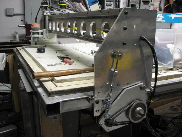
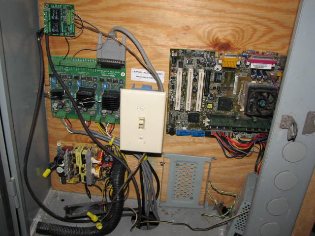
Hi there guys,· This is my latest project.· A Router/Laser CNC Table, I will include a BS2 Controller to communicate between the driver and the hand held controller. this is a 3 weeks project so far, and I am loving every minute of it.
Now I am not a Mathematician as I pointed many times, so I need help here.
I Move the Z axis 1" exactly (measured by a caliper)
the program read that it has moved o.621"
and the steps required to get there is 76,000 steps in 1/8 step
if I use full step,· the Z axis moves 1.247", the program displays 1.007368 with 7,600 steps
problem...·· and Question.
how many steps do I have to enter so the actual travel and the program read the same amount, either in full or 1/8 th step?
(reply with a simple answer, following by any formula you may want to provide.)
Also..
I haven't purchased the power supply yet, but I am using this 12 Volt, 1 amp power supply
it actually delivering 15.3 volts.· The Drive card takes 12 volt minimum to 24 volts.· at 6 amps max. (PWM)
·http://forums.parallax.com/showthread.php?p=641371·= $10 Stepper motor Controller
·http://forums.parallax.com/showthread.php?p=641605·= Serial to paraller expander
·http://forums.parallax.com/showthread.php?p=637017·= Robotic arm
now...· the transformer is getting warm, and I expect so, not been a real CNC stepper motor, driver power supply and all....· But why are the stepper motors getting Warm too?·· they are rated 5.5 volts 1.5 amp.·· the driver is set to deliver 2.5 volts in bi-polar mode· X2 = 5 Volts· and the amps can't be more than 1 because of the type of power supply it is..··· I am puzzled.·· help....·· please.
http://www.youtube.com/watch?v=LGQ7sTf4diM·· (CNC Routing part)
http://www.youtube.com/watch?v=Xj86rqmcctM·· (Finished part)
http://www.youtube.com/watch?v=BLULfaNhOFg· (first movement)
▔▔▔▔▔▔▔▔▔▔▔▔▔▔▔▔▔▔▔▔▔▔▔▔
Fernando Gomez
·http://pinellas-sign-manufacturer.com
Never compare yourself with anyone else, there will always be someone bigger·or·smaller·than you.
Post Edited (willy1067) : 2/12/2009 12:02:07 AM GMT
480 x 640 - 41K
480 x 640 - 43K
640 x 480 - 61K
640 x 480 - 49K
640 x 480 - 74K
Comments
just to get the numbers right
Real movement Program read out Steps(1/8) Steps(full)
1" 0.621" 76000 9500 (=76000 / 8)
1.247" 1.007368" 60800(=7600*8) 7600
Q1: do I have the numbers right?
Q2: what defines the program read-out? Shouldn't there be a straight relation between steps and read-out ?
regards, Ed
first of all stepper motors can get hot, as long as you can still put your hand on them , they arent too hot
they can be overdrivin with voltage with no harm, just limit your current to the max your motor calls for
i'm currently running 29 volts on 6 volt motors ( faster response)
as for math just know your steps / rev of your motor and multiply it by your threads per inch (TPI)
for example if you hook up a 200 step/rev ( 1.8 deg ) motor to a 1/4-20 allthread ( 20 tpi) just multiply
200 * 20· = 4000 steps / inch in fullstep, 8000 in halfstep, etc
i use driver boards that this guy made , he has some good info and you can get the boards pretty cheap too
http://www.pminmo.com/phpBB/
hope this helps
dan
ps im using 3 computer power supplys in series, theres docs at above links to show you how
looks to me like your loosing steps, due to not having enuf voltage to your motors most of those driver boards have a place that you can measure and limit your current
·so i would say to hook up a power resistor to a extra computer power supply and use it...
Post Edited (Sawmiller) : 6/17/2007 12:12:10 PM GMT
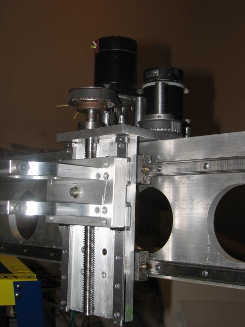
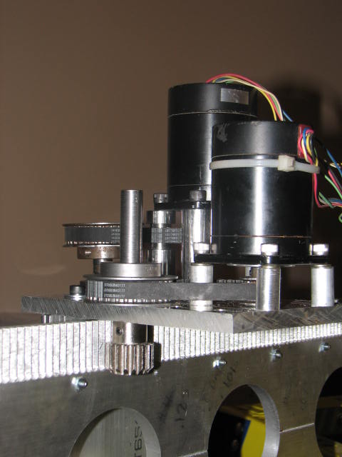
About your calculation of steps and threads... there is another calculation to be added, as you can see in the X axis picture, both Z and X are using a timing pulley with a reduction of 3 to 1 connected with a 50 tooth belt.
My 3 axis board from Mechatronics uses a single power supply line, so one power supply will do fine. I did considered connecting a PC power supply, but after reading a little more into it, the amount of amps that the units produces may damage my board which is rate for up to 6 amps only.
My stepper motors are only 5.5 volts and 1.5 amps... so a 12 volt 4 amp will do nice keeping my board happy within the limits. and yes the board lets me control the voltage and current for each motor.
Ed.
I will make sure I am not loosing steps as Dan suggested before answering your question, but as I mentioned above...
the Z axis actual movement at full steps is 1.247 while the program calculates that it has only moved 1.0073 counting 7,600 steps.
Now... if I use 1/8 steps, the computer calculates that it has only moved only 0.621 counting 76,000 steps. while that 1" has been achived.
I will play with the numbers Monday. I want to be able to go either full or 1/8 step, that way I can do things fast and less accurate or slow, and very accurate.
I will post an answer late Monday. Thanks both of you, the help is greatly appreciated.
▔▔▔▔▔▔▔▔▔▔▔▔▔▔▔▔▔▔▔▔▔▔▔▔
Fernando Gomez
revinc.us
gomez-rivera.com
Never compare yourself with anyone else, there will always be someone bigger·or·smaller·than you.
Sid
▔▔▔▔▔▔▔▔▔▔▔▔▔▔▔▔▔▔▔▔▔▔▔▔
Yesterday is history, tomorrow is a mystery, and today is a gift.
That is why they call it the present.
Don't have VGA?
Newzed@aol.com
·
Sid
▔▔▔▔▔▔▔▔▔▔▔▔▔▔▔▔▔▔▔▔▔▔▔▔
Yesterday is history, tomorrow is a mystery, and today is a gift.
That is why they call it the present.
Don't have VGA?
Newzed@aol.com
·
Got a better power supply and tried your equation, with a little ajustment to it.
It's 200 step for the motor X3 for the pulley X10 for the threads. So 200x3=600x10=6,000 steps to move Z 1". Thanks
Penguin
I myself am using KCam4 for routing, it's free for 60 days and if I deside to purchase it, it's only $99.00.
The graphic, I can do it in corel, Auto Cad, Flexi or Gerber, then export it to KCam in DXF format.
Now will work on X. next week on Y.... then on the BS2 controller program. I will keep you posted guys. so exited...
▔▔▔▔▔▔▔▔▔▔▔▔▔▔▔▔▔▔▔▔▔▔▔▔
Fernando Gomez
revinc.us
gomez-rivera.com
Never compare yourself with anyone else, there will always be someone bigger·or·smaller·than you.
Post Edited (willy1067) : 6/18/2007 11:59:16 PM GMT
i use a pulley belt setup too... 200 step motor to 15:25 pulley to 3/8-16 allthread....1920 steps/inch in full step dont forget you lose a lil torque in anything other than full step
i'm using mach 3, great program and currently rebuilding my z axis for more rigidity.
take care
dan
Do you assume than you were losing steps because of a poor power supply?
▔▔▔▔▔▔▔▔▔▔▔▔▔▔▔▔▔▔▔▔▔▔▔▔
Timothy D. Swieter
tdswieter.com
One little spark is all it takes for an idea to explode
to cut a square:
G01X-.5Y0
G01Y-1
G01X1
G01Y1
G00X0Y0
GO1 is a move while cutting and G00 is rapid ect,
also there is M01 M30 ect..
im just curious as to how the cnc machines you guys are building are run, and programmed.
I have seen CNC come up alot on the forum, some use their own software some convert it to G code. I use Alibre Design it is a Cad/Cam software and it not to expensive. Others use ArtSoft 6 Axis and it will be my next software on my plasma table and its not to expensive and it can take a .bmp and convert it to G code which is nice.
Yes, the Z and X Axis are moving already, this weekend I will build the table (4' x 8') then work on the Y.
I was loosing steps for various reasons.
1. I was trying to move too fast. 120" per minute
2. When using 1/8 step, I was loosing torque (as Dan mentioned above)
and 3. My power supply was not producing enough amps to run both the controller and the motor.
Penguin,
I prefer to use programs like CorelDraw to make my graphics for parts, if I am using to rout signs, then I use FlexiSigns or Gerber Edge.
there are tons of programs out there that convert, DXF, AI or EPS files to gcode for you. once saved in Gcode, just route it using Kcam or March3.
more expencive programs produce their own gcode.
Bennettdan,
I will download and try those software, to see how they are. always trying new things.
Post Edited (willy1067) : 12/12/2008 9:38:03 PM GMT
http://forums.parallax.com/showthread.php?p=637017
http://www.youtube.com/watch?v=LGQ7sTf4diM·· (CNC Routing part)
http://www.youtube.com/watch?v=Xj86rqmcctM·· (Finished part)
http://www.youtube.com/watch?v=BLULfaNhOFg· (first movement)
I just created the youtube account and the video is not yet processed, but hopefully withing few minutes you be able to see it.
www.pinellas-sign-manufacturer.com
▔▔▔▔▔▔▔▔▔▔▔▔▔▔▔▔▔▔▔▔▔▔▔▔
Fernando Gomez
Never compare yourself with anyone else, there will always be someone bigger·or·smaller·than you.
Post Edited (willy1067) : 12/12/2008 10:22:06 PM GMT
▔▔▔▔▔▔▔▔▔▔▔▔▔▔▔▔▔▔▔▔▔▔▔▔
Timothy D. Swieter, E.I.
www.brilldea.com - Prop Blade, LED Painter, RGB LEDs, uOLED-IOC, eProto for SunSPOT, BitScope
www.tdswieter.com
Cool project!!!!
I'm working on a N.C. control for My Vert.Mill (3 axis) and I could really use some help with it.
I would like to use a BS2OEM for this project as it would make it easyer to make a custom board.
If You don't mind sharing a little more info on Your project;
1 ·Are You positioning the steppers with out·a "PID" type controller?
2 If so how are You handling the over/under errors?
I liked the MOSFET drivers.
I watched the You Tube flicks and all I can say is Awesome!!
____________$WMc%__________________Merry Xmas
▔▔▔▔▔▔▔▔▔▔▔▔▔▔▔▔▔▔▔▔▔▔▔▔
The Truth is out there
Post Edited ($WMc%) : 12/14/2008 11:54:10 PM GMT
Thanks for the cudos !!!
I purchase a CNC controller form Ebay, ($69) and because the table is 4' x 8' I have the BS2 receiving the Y signal and outputing it to two stepper motors on the sides (I figure that that would keep the Y axis Square and reduce the torque.)
also the BS2 helps me find the tool position. I will post the code as soon as I am done writing it.
(not really a programmer, lol
for positioning I will use encoders, but not there yet; and because of that·I miss some steps from time to time.
·http://pinellas-sign-manufacturer.com
▔▔▔▔▔▔▔▔▔▔▔▔▔▔▔▔▔▔▔▔▔▔▔▔
Fernando Gomez
Never compare yourself with anyone else, there will always be someone bigger·or·smaller·than you.
Post Edited (willy1067) : 12/16/2008 12:48:58 AM GMT
I must say your router looks like a lighter 'laminate router' that may not hold up over the long haul. For deep cuts and harder material, the larger routers are necessary. Just make sure everything [noparse][[/noparse]including the cutting bits] are bolted down tight or material and things start to fly around.
▔▔▔▔▔▔▔▔▔▔▔▔▔▔▔▔▔▔▔▔▔▔▔▔
How do you like my name change?
aka G. Herzog [noparse][[/noparse] 黃鶴 ] in Taiwan
Cool,I can't wait to see it.
I'm stuck at the CNC "software to Hardware" point. I'm not sure what the CNC software wants to see as far as a driver goes?
__________$WMc%_____________Merry Xmas_______P.S. Is that Pinellas Co.,Fl.?
▔▔▔▔▔▔▔▔▔▔▔▔▔▔▔▔▔▔▔▔▔▔▔▔
The Truth is out there
Very cool!
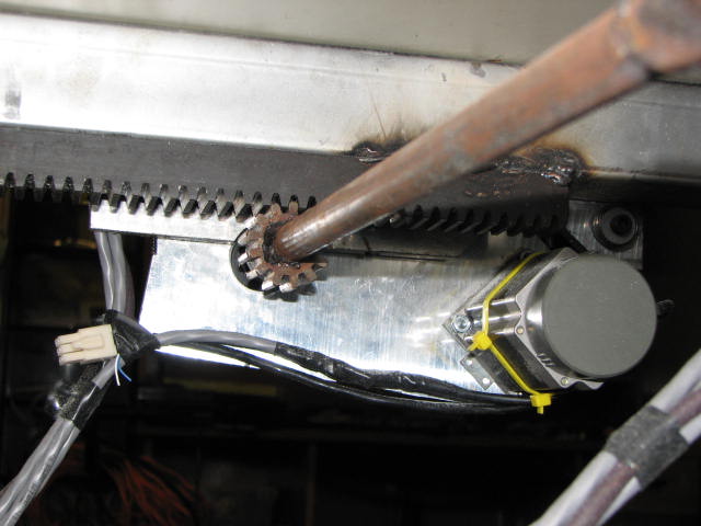
One of the first "CNC self modifications" I want to do with a CNC of my own is to create a rack and pinion style of linear travel similar to what you have setup. Does the Y axis also have a rack and pinion on the back side of the picture you are showing for the Z axis?
▔▔▔▔▔▔▔▔▔▔▔▔▔▔▔▔▔▔▔▔▔▔▔▔
Beau Schwabe
IC Layout Engineer
Parallax, Inc.
______________$WMc%_____________Merry Xmas
▔▔▔▔▔▔▔▔▔▔▔▔▔▔▔▔▔▔▔▔▔▔▔▔
The Truth is out there
$WMc%; you can download a free trial of KCam and use it for 90 days, and use any program that create DXF or HPGL or PL format to route.
and yes, pinellas Co, in Tampa Florida. (my own little shop)
Beau; I am using rack and pinion for both the X and Y, but for the Z; I am using lead screw, even tho it's slower, it has more power (bite) and· better precision.
I will post another picture of the Y axis rack and pinion tomorrow.
P.S. there is a 3 axis board with power supply and 1 motor on Ebay for $51 so far (great deal)
·http://cgi.ebay.com/Mini-Milling-Machine-Controller-X-Y-Z-Motor-CNC-NR_W0QQitemZ270323419459QQcmdZViewItemQQptZLH_DefaultDomain_0?hash=item270323419459&_trksid=p3286.c0.m14&_trkparms=72%3A1205%7C66%3A2%7C65%3A12%7C39%3A1%7C240%3A1318%7C301%3A0%7C293%3A1%7C294%3A50
Any of you guys are programmers for the BS2?· I need help with another project.
▔▔▔▔▔▔▔▔▔▔▔▔▔▔▔▔▔▔▔▔▔▔▔▔
Fernando Gomez
·http://pinellas-sign-manufacturer.com
Never compare yourself with anyone else, there will always be someone bigger·or·smaller·than you.
Post Edited (willy1067) : 1/2/2009 8:38:14 AM GMT
posted new pictures
▔▔▔▔▔▔▔▔▔▔▔▔▔▔▔▔▔▔▔▔▔▔▔▔
Fernando Gomez
·http://pinellas-sign-manufacturer.com
Never compare yourself with anyone else, there will always be someone bigger·or·smaller·than you.
Have You posted any code for the CNC project?
The PICs where cool.
Send a link for the new project and I'll Try to help!
_________________$WMc%___________
▔▔▔▔▔▔▔▔▔▔▔▔▔▔▔▔▔▔▔▔▔▔▔▔
The Truth is out there············································ BoogerWoods, FL. USA
Post Edited ($WMc%) : 2/12/2009 2:59:10 AM GMT
I am still working mostly in the hardware first, next are the decoders, then programing BS2 for various things.
▔▔▔▔▔▔▔▔▔▔▔▔▔▔▔▔▔▔▔▔▔▔▔▔
Fernando Gomez
·http://pinellas-sign-manufacturer.com
Never compare yourself with anyone else, there will always be someone bigger·or·smaller·than you.
I Almost have a router table made. Just waiting on a few bearings. And hopfully I can get in on the CNC projects.
My Table will use just a Sharpe at first and then I might add a Dremmel tool.
All Of this is really for My Vert. Mill.
It sounds like Your as tied up in other things as I am. Its just hard to find the time to really roll with some projects!!!!.
______________$WMc%_________________
▔▔▔▔▔▔▔▔▔▔▔▔▔▔▔▔▔▔▔▔▔▔▔▔
The Truth is out there············································ BoogerWoods, FL. USA
Busy, Busy with my business and others things... You know how it's.
and I just wrote the patents for my robotic arm, and few people are approaching me with money to build them. So I will be even busy-err..r.
·http://forums.parallax.com/showthread.php?p=637017
I also added a Laser to the table, so now I can route with the router, and cut/emgrave with the laser, very exciting things comming out of the table. Check my website.
Thanks for keeping the post alive.
▔▔▔▔▔▔▔▔▔▔▔▔▔▔▔▔▔▔▔▔▔▔▔▔
Fernando Gomez
·http://pinellas-sign-manufacturer.com
Never compare yourself with anyone else, there will always be someone bigger·or·smaller·than you.