

6502 board experiment
 Lord Steve
Posts: 206
Lord Steve
Posts: 206
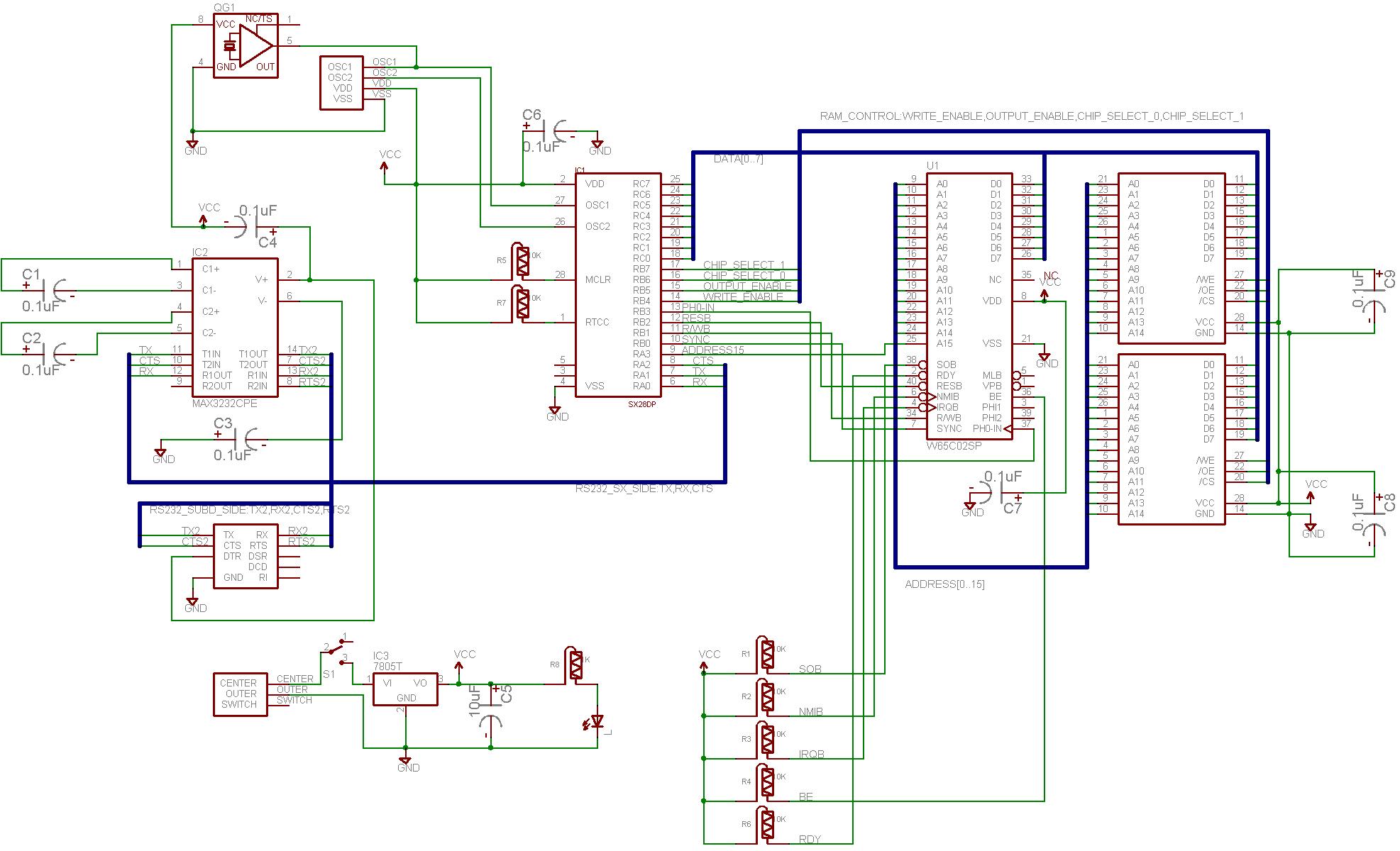
My first real PCB project...a board with a 65c02, 64K RAM, SX28 microprocessor w/ programming header, MAX3232-a-like, RS-232 via 9-pin female SUB-D connector, etc.· The SX28 clocks the CPU, decodes the A15 address line to select the right chip, and handles the read/write control signals for the RAMs.· Since the 6502 has no built-in debugging functionality, the SX28 handles single instruction stepping·by watching for the CPUs SYNC signal to assert, which means it is fetching an opcode from· memory.· The SX28 clocks the CPU so it has automatic synchronizatio/knowledge.· The SX is interfaced to the 6502's databus, so it can watch for special opcodes such as "BRK" (the software bearkpoint) and "COP" (the coprocessor instruction).· The SX28 can also peek and poke memory/registers by giving the CPU instructions to do so.· For RAM, this means saving IO pins by not requiring the address lines to interface directly.
The schematic and board were·designed in EAGLE from CadsoftUSA and I HIGHLY recommend it.· The board was made with SparkFun's protoboard service, www.BatchPCB.com, which I also recommend.· This double-sided, 4"x2" board cost me only $20.
By doing this board I learned a lot about my cad program (making part libraries, heeding design rule checks, going from schematic to board) and the 6502 processor·(including instruction timing, resetting the CPU, circuit interfation--I made that word up).
I am not prepared to release source code at this time.· Comments on the schematic are welcome; it's my first real PCB project.

615 x 461 - 93K
1973 x 1200 - 231K
Comments
▔▔▔▔▔▔▔▔▔▔▔▔▔▔▔▔▔▔▔▔▔▔▔▔
Whit+
"We keep moving forward, opening new doors, and doing new things, because we're curious and curiosity keeps leading us down new paths." - Walt Disney
Post Edited (Lord Steve) : 6/16/2007 10:54:56 PM GMT
Haha, you know I actually never thought of that? If you're doing what I'm doing (I think so), what I was trying to do was use the address lines from the 6502 to avoid having to address the RAM with my microcontroller. The idea is that if you can trick the 6502 into going to some address, you can have the 6502 address RAM for you while you read or write that RAM with the microcontroller. The way I planned to do it is that when you reset the 6502 it tries to read a reset vector address out of ROM, but instead of getting that from memory we feed the 6502 "bull(expletive)" data on the bus that tells it to go to the address we want. Once there, you can keep sending the 6502 NOP codes to increment the address, while reading/writing to memory yourself.
The thing I didn't think of, is that it never occured to me that I could just let the 6502 free-run at full speed while I do all this. Certainly my RAM and microcontroller are fast enough to do the job, but I just assumed from the beginning that I would be using the single-machine-cycle feature and single stepping through this process at low speed instead of intercepting the signals in real time. That's why it taking me so long to design the circuit.
Using the Rdy signal to single step the 6502, at least with the non-CMOS old original 6502 I have, is not easy because it seems that asserting Rdy at the wrong time can actually lock up the processor hardware! Even though you may be listening for Sync before you assert Rdy, you absolutely must also synchronize that action with the correct phase of the clock. And then you also have the problem that you can't just use logic gates alone because the circuit must make different outputs for the same set of inputs - it has to be a state machine and remember its current state (triggered or not triggered) when deciding what to output. I built a state machine out of two cross-connected flip flops, and actually that did the job very nicely, but I wanted to simplify the circuit before I moved it from the breadboard to soldering it. I figured out that it would be possible to write software for the microcontroller that would do the job formerly done by the complex physical flip-flops circuit. The trouble is, although I am trying to make my software "emulate" the signals and timing of the physical flip-flop state machine I replaced, I haven't been successful doing it in software, and I don't know why not. So I was wondering if you had any insight, but I ended up being the one who had more information on it after all. If you're interested, I have a blog posting that talks about it a little too: dennisferron.blogspot.com/2007/04/i-like-that-old-time-rock-and-roll.html
Seriously though, what you've done here is super-cool. Please, tell us more about your project! How do you load code into the RAM? How does the 6502 communicate with the world? Do you have the SX intercept reads and writes to certain memory locations? Any plans for making a tiny OS to run on it?
Cool stuff. I spent years working on projects with my self designed 6502 boards. When I started, my entire debugging arsenal consisted of a logic probe. What I would have given to be able to single step code back then...
Thanks,
PeterM
I started serious programming·with Borland Turbo C++ in the mid '90s and so I have always had a decent debugger around to hold my hand.· I don't like thinking about debugging without them. [noparse]:)[/noparse]
Dennis,
You are making life too hard on yourself.· The SX in my design CLOCKS the 6502, so I don't have to mess around with RDY signals, or flip-flops, or·AND gates, oh my.· The SX initiates the clock cycle with the falling edge of the clock and examines the output signals that it cares about.· If single-stepping, it looks for SYNC asserted;·every cycle, it looks at A15 to determine which of two RAM chips to enable /CS for; etc.·Though, I didn't include it on this board, the idea was to load a 64KB serial EEPROM from a host through the serial port to hold the program; then when the board would be booted the SX would bootload the RAM from that EEPROM.· I liked that because then you have all RAM, which is more versatile, and don't have to worry about inserting wait states when reading from a ROM.· (It's easy enough to do, especially with an SX governing the 6502, but why do it if you don't have to?)· I use fast 10-25ns SRAM.· The 6502 does not talk to the outside world.· This board was made just to have fun with the idea of the SX driving the 6502.
I think engineers from the days when the 6502 came out would have killed to have access to the kind of SRAM chips we can get today. I'm using RAM chips that used to be cache-RAM on old 486 boards that ran at 100 MHz. 10ns read/write, great stuff.
In my design I'm using a Propeller because the Propeller can also serve as a versatile Input/output chip. It can generate TV-out, talk to a mouse and keyboard, etc., all at once. Especially if you make a second version, or even if you want to add a peripheral board to make this unit stand on its own, then you should definitely take a look at the Propeller. At first I thought that having the Propeller on the board would make the 8-bit processor on my board redundant - that's simply not the case. The Propeller architecture is just so different from an "ordinary" processor that they fill very different niches. So from an aethestic standpoint, I don't think the Propeller makes the 8-bit processor obsolete at all. I think they complement one another nicely.
This looks like a very fun project...
Do you think you could post the source and whatever files I would need to order the PCB ?
▔▔▔▔▔▔▔▔▔▔▔▔▔▔▔▔▔▔▔▔▔▔▔▔
Living on the planet Earth might be expensive but it includes a free trip around the sun every year...
Experience level:
[noparse][[/noparse] ] Let's connect the motor to pin 1, it's a 6V motor so it should be fine.
[noparse][[/noparse] ] OK, I got my resistors hooked up with the LEDs.
[noparse][[/noparse]X] I got the Motor hooked up with the H-bridge and the 555 is supplying the PWM.
[noparse][[/noparse] ] Now, if I can only program the BOE-BOT to interface with he Flux Capacitor.
[noparse][[/noparse] ] I dream in SX28 assembler...
/Bamse
I'm working on·a USB version when time permits.· Would you be interested in that?· It should be superior than the current board (which has errors on it).· I have not had the corrected version of this board made, so I am hesitant to release it.
Thanks for your interest.· [noparse]:)[/noparse]
USB would be even better since I only have one Serial port and it's already taken...
▔▔▔▔▔▔▔▔▔▔▔▔▔▔▔▔▔▔▔▔▔▔▔▔
Living on the planet Earth might be expensive but it includes a free trip around the sun every year...
Experience level:
[noparse][[/noparse] ] Let's connect the motor to pin 1, it's a 6V motor so it should be fine.
[noparse][[/noparse] ] OK, I got my resistors hooked up with the LEDs.
[noparse][[/noparse]X] I got the Motor hooked up with the H-bridge and the 555 is supplying the PWM.
[noparse][[/noparse] ] Now, if I can only program the BOE-BOT to interface with he Flux Capacitor.
[noparse][[/noparse] ] I dream in SX28 assembler...
/Bamse