

TV Broadcast using TV_Text
 tatatom
Posts: 16
tatatom
Posts: 16
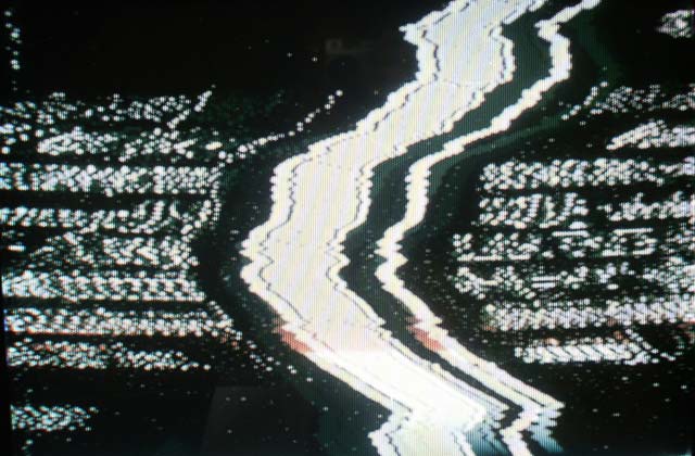
I am This close to using the TV broadcast option but no matter what I try I can't get it any better than the attached image. It works perfectly with just a cable and composite input to the TV but no matter what TV or what settings I try this is as close as it comes.
I'm using a homemade board modeled after the Demo board.
Below are the TV_Params settings from TV.spin. Any help or suggestions would be most appreciated because at this point I'm stumped.
Thanks
Tom
++++++++++++++++++++++++++++++++++++++++
tv_params long 0 'status
long 1 'enable
long %10100 'pins
long %10010 'mode
long 0 'screen
long 0 'colors
long cols 'hc
long rows 'vc
long 4 'hx
long 1 'vx
long 0 'ho
long 0 'vo
long 55_250_000 'broadcast
long 0 'auralcog
640 x 420 - 54K
Comments
See if this thread helps:
http://forums.parallax.com/showthread.php?p=593861
I'll be trying this in the next few weeks, so keep us posted on your results. Also there was another thread that talked about using a 6 MHz crystal:
http://forums.parallax.com/showthread.php?p=651266
▔▔▔▔▔▔▔▔▔▔▔▔▔▔▔▔▔▔▔▔▔▔▔▔
Mike
Post Edited (Mike Cook) : 6/3/2007 1:30:01 PM GMT
i have the same problem.
I tryed all the settings, and only got a picture like you.
I almost think that it has some to do with the tv.
Do you use a TV antenna.
Anubisbot
Yes I have antenna on both the TV and the Prop board.
I changed the mode to %11110 as per Mike Green for colour suppressing
I changed the freq to 60_000_000 (and many variations between 55_250_000 and 60)
I tried on 4 different TVs
and no difference.
As for 6 mhz crystals I don't have any and it seems like it does work for some with the standard 5 mhz
So what's next to try?
Tom
Sid
▔▔▔▔▔▔▔▔▔▔▔▔▔▔▔▔▔▔▔▔▔▔▔▔
Yesterday is history, tomorrow is a mystery, and today is a gift.
That is why they call it the present.
Don't have VGA?
Newzed@aol.com
·
Do you have a photo of your board, specialy where the antenna and the 3to4 resistors are..
@newzed
we try to broadcast
Anubisbot
Yup Same results here, using the following:
P12 - 1.2K
P13 = 560
P14 - 270
P15 - 560
Tried both 5 and 10 MHz crystals, don't have a 6 MHz on hand,
Set Mode to %11010
Tried 55_250_000, 60_000_000, 61_250_000 for Broadcast, using a Parallax ProtoBoard, Stock#: 32212.
Only way I can get a picture is to wrap the antenna wire around the TV's antenna. Boy thought this would be easy!
▔▔▔▔▔▔▔▔▔▔▔▔▔▔▔▔▔▔▔▔▔▔▔▔
Mike
So now where does all this leave us?
Tom
Tom
Sid
▔▔▔▔▔▔▔▔▔▔▔▔▔▔▔▔▔▔▔▔▔▔▔▔
Yesterday is history, tomorrow is a mystery, and today is a gift.
That is why they call it the present.
Don't have VGA?
Newzed@aol.com
·
Sid,
I would have to agree that a video transmitter, to transmit the Propellers composite output, for longer distances would be the way to go.
However according to the data sheet for the Propeller and the documentation provided in the TV.spin object, it states "Wireless video transmission (NTSC or PAL)", directly from the chip, that's what we are trying to accomplish.
My needs are for short range transmission, 2 to 6 feet would be adequate, with out any additional hardware, besides the resistors needed for the broadcast output, and maybe substituting a different crystal than what's·provided with the Propeller ProtoBoard.
▔▔▔▔▔▔▔▔▔▔▔▔▔▔▔▔▔▔▔▔▔▔▔▔
Mike
Post Edited (Mike Cook) : 6/3/2007 7:05:35 PM GMT
Tom
Tom
Your picture in the top of this thread, seems to have the horizontal sync pulses inverted.
Check this inside the TV with a oscilloscope.
Perhaps your video signal is correct, but your broadcast signal is not..[noparse]:)[/noparse], check this please ("luminance signal").
Maybe an incorrect channel syntonized could do that too. Maybe you're syntonizing an 'armonic' of the RF signal.
▔▔▔▔▔▔▔▔▔▔▔▔▔▔▔▔▔▔▔▔▔▔▔▔
Regards.
Alberto.
▔▔▔▔▔▔▔▔▔▔▔▔▔▔▔▔▔▔▔▔▔▔▔▔
Paul Baker
Propeller Applications Engineer
Parallax, Inc.
Sid
▔▔▔▔▔▔▔▔▔▔▔▔▔▔▔▔▔▔▔▔▔▔▔▔
Yesterday is history, tomorrow is a mystery, and today is a gift.
That is why they call it the present.
Don't have VGA?
Newzed@aol.com
·
In the unmodified file (TV_Text.spin)·it is set to 0, I·tried the following values:
Channel      Frequency
-------      ---------
2            55_250_000
             60_000_000
3            61_250_000
4            67_250_000
▔▔▔▔▔▔▔▔▔▔▔▔▔▔▔▔▔▔▔▔▔▔▔▔
Mike
Post Edited (Mike Cook) : 6/5/2007 12:43:00 PM GMT
Sid
▔▔▔▔▔▔▔▔▔▔▔▔▔▔▔▔▔▔▔▔▔▔▔▔
Yesterday is history, tomorrow is a mystery, and today is a gift.
That is why they call it the present.
Don't have VGA?
Newzed@aol.com
·
Should be in your Propeller Tool folder, but here it is attached, this one is from the 1.0 Propeller Tool
▔▔▔▔▔▔▔▔▔▔▔▔▔▔▔▔▔▔▔▔▔▔▔▔
Mike
FYI:
The TV I'm using to receive the signal with is a cheap Walmart 13" color TV about 4 years or so old. It has a whip antenna that can be attached to the TV's RF 'F' connector. In the TV's menu option, I have it programmed for OFF AIR, instead of CATV, actually tried both settings. I have a little B&W 'tunable' 5" TV at work, I'll bring that home and try with that TV. But to be 'usable' I really need it to work with about any, off the shelf, modern TV.
Thanks for looking into this, have you had a chance to read my PM?
▔▔▔▔▔▔▔▔▔▔▔▔▔▔▔▔▔▔▔▔▔▔▔▔
Mike
i dont know how the modulation works on the chip but id imagine you can change the frequency.
Attached is a picture of the TV and the file used in conjunction with the TV_Text_Demo.spin
▔▔▔▔▔▔▔▔▔▔▔▔▔▔▔▔▔▔▔▔▔▔▔▔
Paul Baker
Propeller Applications Engineer
Parallax, Inc.
If possible, can you:
1. Try it on a Proto Board
or
2. Using the demo board, Install the three resistors that make up the TV interface on the Demo Board's plastic bread board area, and then change the pins that the object uses? I'd do this but have never purchased a demo board, just have chips and Proto Boards.
I opened another NEW Proto Board and installed the three resistors.
P12 = 1.2
P13 = 560
P14 = 270
Still have the same quality picture as Tom's as shown in his first post. However no picture on channel 3 but have a torn, somewhat color picture on channel 2,.
The Demo Board schematic has the resistor for P12 as a 1.1K, could that be causing the issue? I would like to see this work on the Parallax Propeller Proto Boards.
Thanks for your help.
▔▔▔▔▔▔▔▔▔▔▔▔▔▔▔▔▔▔▔▔▔▔▔▔
Mike
Post Edited (Mike Cook) : 6/5/2007 11:17:04 PM GMT
▔▔▔▔▔▔▔▔▔▔▔▔▔▔▔▔▔▔▔▔▔▔▔▔
Paul Baker
Propeller Applications Engineer
Parallax, Inc.
Yes I did, used your TV_TEXT.spin, the TV.Spin from the Propeller Tool 1.05.5, and a simple top file that I created. Archive attached along with a few photos.
The TV has a whip antenna, I used an insulated wire, on the Propeller Proto Board as it's antenna, about 24" long, this was connected to the junction of the three resistors that would normally connect to the center pin of a RCA jack. Only way I can get any picture is to wrap the insulated antenna wire coming from the Propeller Proto Board around the TV's whip antenna. Nothing displayed on channel 3, but got the picture as attached, on channel 2.
I changed the line in your TV_TEXT.spin from:
······················· long··· 60_000_000·············· 'broadcast
to
······················· long··· 0·············· 'broadcast
Recompiled, connected to the composite input of the TV and a perfect picture as I expected.
▔▔▔▔▔▔▔▔▔▔▔▔▔▔▔▔▔▔▔▔▔▔▔▔
Mike
Post Edited (Mike Cook) : 6/5/2007 11:46:15 PM GMT
▔▔▔▔▔▔▔▔▔▔▔▔▔▔▔▔▔▔▔▔▔▔▔▔
Paul Baker
Propeller Applications Engineer
Parallax, Inc.
Well since 60 MHz not a 'real' TV frequency, I tried with 61_250_00 (61.250Mhz) picture is some what better on this board. Is there anything different about your TV_TEXT.spin besides the parameter in the tv_params section?
On the first NEW Propeller Proto Board I tried this on, I used all 4 resistors, and could never get it to work properly using broadcast, but it would work well in composite mode.
P12 - 1.2
P13 - 560
P14 - 270
P15 - 560
The first NEW Propeller Proto Board I tried this on, failed with in 30 minutes, it will identify and program but no TV output, composite or broadcast. Looks to be a PLL failure,·I sent you the details in a PM. Hope this second board will run longer than 30 minutes!
I'll keep tinkering with the frequency, I tried the Incremental Video frequency for channel 3 (61.2625MHz) and this did clean up the picture, not as good as a direct connect but looks like I can get a few feet with it now.
Actual TV looks a little better in 'real life' than the photos, TV's don't photograph very well!
▔▔▔▔▔▔▔▔▔▔▔▔▔▔▔▔▔▔▔▔▔▔▔▔
Mike
Post Edited (Mike Cook) : 6/6/2007 1:38:30 AM GMT
I downloaded and ran your TV_Text and get the same garbled results on either channel 2 or 3.
Tom
Sid
▔▔▔▔▔▔▔▔▔▔▔▔▔▔▔▔▔▔▔▔▔▔▔▔
Yesterday is history, tomorrow is a mystery, and today is a gift.
That is why they call it the present.
Don't have VGA?
Newzed@aol.com
·
Sid,
In your top file, for example: TV_Text_Demo.spin located in your:
C:\Program Files\Parallax Inc\Propeller Tool v1.0\Examples\Library
Directory, if you installed the Propeller Tool with the defaults.
In the method PUB start, change:
text.start(12)
To
text.start(0)
To have the TV interface starting on pins 0..3. Then the value of resistors should be:
P0 - 1.1K
P1 - 560
P2 - 270
P3 - 560 (optional)
▔▔▔▔▔▔▔▔▔▔▔▔▔▔▔▔▔▔▔▔▔▔▔▔
Mike