

"Prop Dongle" Protoboard 1.5" x 2.75". Available for purchase!
 Bean
Posts: 8,129
Bean
Posts: 8,129
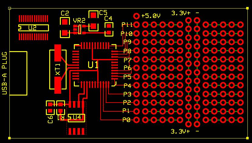
I got this idea to make a Prop Dongle. A very small propeller development board that plugs right into a USB port (or you could use a USB extension cable) and is powered by the USB, has 12 I/Os and a small prototype area.
I will probably build some for myself, but was wondering what you guys think of it. Too small ? Too large ?
It is 2.75" x 1.5"
U1 is the propeller, U2 is FT232RL, U4 is 128KB eeprom.
[noparse][[/noparse]edit] See further down for updated pictures.
Bean.
·
▔▔▔▔▔▔▔▔▔▔▔▔▔▔▔▔▔▔▔▔▔▔▔▔
“The United States is a nation of laws -· poorly written and randomly enforced.” - Frank Zappa
- - - - - - - - - - - - - - - - - - - - - - - - - - - - - - -
www.hittconsulting.com
Post Edited (Bean (Hitt Consulting)) : 6/25/2007 8:45:18 PM GMT
829 x 470 - 87K
Comments
It's a great idea although I would prefer to see more I/O pins available. It's a Prop version of a BS1USB.
I've got a similar module (MoBoProp) in proto form. It's 2.75" x 1.35", can be powered from the USB port, and accepts Parallax's standard daughterboards (including the PropCAM). The photo shows it alongside the Parallax Proto-DB prototyping daughterboard. I need to make a couple changes, though. The A/V connector (a 3/32" stereo phone jack) has not proven itself to my satisfaction, nor has the A/D converter section.
But the fact that you're thinking along similar lines tells me the basic concept is sound!
-Phil
I like yours too and it may be more versatile for the sort of things I have in mind. The Proto-DB is cheap enough for building temporary projects. I do like the idea of having more I/O (including A/V) available. Do you include a Prop A/D converter? Those really have to be planned in because of the noise and lead length issues.
Mike
Thanks! Yes, there's a Prop-based A/D section (lower-right corner of the board), capable of two channels for each daughterboard. It was designed in before the advantage of balanced caps was demonstrated, so it only has caps to ground. That's something I need to address in the next rev. Frankly, I'm not terribly enthused about doing A/D this way, but there just isn't room for anything else...
-Phil
I like you idea of having daughter boards.
I haven't heard about the "balanced caps" method. Where is it posted ?
I wanted something cheap and simple, I was going to put more I/Os on the other side, but I was afraid it was getting too big. I want to use it like a memory stick. Just plug the board into a USB port on the front of my computer.
I'm making these mainly to use-up the parts I bought for the overlay board. Plus I want to get some experience with the FTDI chips. Most likely I'll make everything freely available on the forum (expresspcb layout, parts list, etc.).
I hope that's not stepping on you're toes Phil ? Let me know if it is, I'll just keep it to myself.
Bean.
▔▔▔▔▔▔▔▔▔▔▔▔▔▔▔▔▔▔▔▔▔▔▔▔
“The United States is a nation of laws -· poorly written and randomly enforced.” - Frank Zappa
- - - - - - - - - - - - - - - - - - - - - - - - - - - - - - -
www.hittconsulting.com
Post Edited (Bean (Hitt Consulting)) : 6/1/2007 6:42:43 PM GMT
You can see these caps in the schematic of the Propeller Demo Board Kit. They're in the microphone input circuit: two 1nF caps, one to Vdd, the other to ground (rather than just one to ground). This is done to make the A/D input more resistant to noise on the 3.3V supply rails.
And don't worry about my toes! The more choices people have, the better!
-Phil
but I don't want to drag down all the little pieces (cables, wall wart, demo board); it would be
nice just to keep one of these in my backpack and shove it into whatever USB port is available.
-tom
That would give you 8 adc ports with only 3 propeller pins in a small form factor.
There's already code for it and it doesn't have the other problems.
I like TI's EZ430-F2013 development board for the MSP-430. $20 and it looks like a USB memory stick.
▔▔▔▔▔▔▔▔▔▔▔▔▔▔▔▔▔▔▔▔▔▔▔▔
Tracy Allen
www.emesystems.com
would be ideal. The smaller, simpler, and cheaper the better. Indeed if these could be made cheap enough, they would give people another
*easy* way into the prop; get one of these now and they'll quickly want to move up to the Demo board, but this will give them a taste without
requiring them to build anything. And in general, once they've had a taste of the prop, they'll want more very quickly.
▔▔▔▔▔▔▔▔▔▔▔▔▔▔▔▔▔▔▔▔▔▔▔▔
Tracy Allen
www.emesystems.com
▔▔▔▔▔▔▔▔▔▔▔▔▔▔▔▔▔▔▔▔▔▔▔▔
Timothy D. Swieter
tdswieter.com
One little spark is all it takes for an idea to explode
I'll keep everyone informed in this thread.
Bean.
▔▔▔▔▔▔▔▔▔▔▔▔▔▔▔▔▔▔▔▔▔▔▔▔
“The United States is a nation of laws -· poorly written and randomly enforced.” - Frank Zappa
- - - - - - - - - - - - - - - - - - - - - - - - - - - - - - -
www.hittconsulting.com
·
Initial reaction was, I like that but what the heck would I use it for? Answer, testing/developing code anytime any place especially with the prop terminal so you don't need a TV with you. For me the smaller the better.
Graham
Seems ashame not to bring the other I/O pins out though...
▔▔▔▔▔▔▔▔▔▔▔▔▔▔▔▔▔▔▔▔▔▔▔▔
www.mikronauts.com - a new blog about microcontrollers
You can cut off the prototype area (making it 1.5" x 1.5"), added two LEDs, reset circuit, connected more of the layout.
John, since this is meant to be used by plugging directly into the USB port on a PC, I doubt I will put mounting holes on it. I really don't have the room anyway.
As always comments welcome, this will become YOUR toy when I'm done.
Bean.
▔▔▔▔▔▔▔▔▔▔▔▔▔▔▔▔▔▔▔▔▔▔▔▔
“The United States is a nation of laws -· poorly written and randomly enforced.” - Frank Zappa
- - - - - - - - - - - - - - - - - - - - - - - - - - - - - - -
www.hittconsulting.com
Post Edited (Bean (Hitt Consulting)) : 6/2/2007 7:46:42 PM GMT
www.serpac.com/products_s-110-i.htm
Simple folded cases are good too, see attached (not mine) and if you want to make a really fancy one check out this cool software:
www.tamasoft.co.jp/pepakura-en/
The gallery is well worth a look at.
If you really want a proper box I suspect you are looking for product built for a different design brief, possibly more like Phil's unit.
Graham
Graham
▔▔▔▔▔▔▔▔▔▔▔▔▔▔▔▔▔▔▔▔▔▔▔▔
Max Wooden
Graham
Please let me know if you see anything not connected correctly. (Sorry I don't have schematic yet, I Know, I know bad form).
[noparse][[/noparse]edit] see further down for updated pictures.
Bean.
·
▔▔▔▔▔▔▔▔▔▔▔▔▔▔▔▔▔▔▔▔▔▔▔▔
“The United States is a nation of laws -· poorly written and randomly enforced.” - Frank Zappa
- - - - - - - - - - - - - - - - - - - - - - - - - - - - - - -
www.hittconsulting.com
Post Edited (Bean (Hitt Consulting)) : 6/4/2007 4:32:47 PM GMT
Graham
Here is an updated layout.
I added a 2-pin header for the TV output.
Only one LED on-board.
Added vias for pins 16-19
Bean.
▔▔▔▔▔▔▔▔▔▔▔▔▔▔▔▔▔▔▔▔▔▔▔▔
“The United States is a nation of laws -· poorly written and randomly enforced.” - Frank Zappa
- - - - - - - - - - - - - - - - - - - - - - - - - - - - - - -
www.hittconsulting.com
If the vias could via into slightly larger pads that would be even better if its possible.
Graham
I think this is the first time a circuit worked the first time.
Forgive my hack-job with the paper cutter.
Only thing is the TV out doesn't have any color ???
Now I used a 220 ohm, 470 ohm, and 1K ohm for the resistors. Do you think that is causing it ?
Graham,
Would you like to play with...I mean test, one of these prototypes ? If so I'll send you one.
Bean.
▔▔▔▔▔▔▔▔▔▔▔▔▔▔▔▔▔▔▔▔▔▔▔▔
“The United States is a nation of laws -· poorly written and randomly enforced.” - Frank Zappa
- - - - - - - - - - - - - - - - - - - - - - - - - - - - - - -
www.hittconsulting.com
Post Edited (Bean (Hitt Consulting)) : 6/8/2007 1:14:26 AM GMT