

Simple problem with program
 Professorwiz
Posts: 153
Professorwiz
Posts: 153
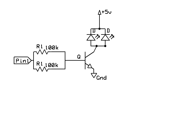
Hello, I've been using PBasic and have just been going though my programs making them work with the SX, I've changed a simple one that flashes a couple led going though a transistor, and one just going though a 470ohm resistor.· The problem is I have 2 programs and one works and one doesn't and I can't see why the 1st doesn't.· My schematic is attached for the pin with the transistor.· Can anyone tell me what I'm overlooking?
Program 1:
'
' Device Settings
'
DEVICE········· SX28, OSCHS3, TURBO, STACKX, OPTIONX
IRC_CAL··IRC_SLOW
FREQ··········· 5_000_000
PROGRAM··start_point
'
' IO Pins
'
'pin0 to transistor and 3 leds
'pin1 to resistor and 1 led
'
' Variables
'
ctn·var·byte
'
TRIS_B=0
RB=0
·'
'··········· PROGRAM CODE
'
start_point:
·for ctn =1 to 10
··RB=%00000000
··pause 100
··RB=%11111111
··pause 100
·next
·goto start_point
Program #2
' =========================================================================
'
'·· File...... TEMPLATE.SXB
'·· Purpose... SX/B Programming Template
'·· Author....·
'·· E-mail....·
'·· Started...
'·· Updated...
'
' =========================================================================
'
' Program Description
'
'
' Device Settings
'
DEVICE········· SX28, OSCHS3, TURBO, STACKX, OPTIONX
IRC_CAL··IRC_SLOW
FREQ··········· 5_000_000
PROGRAM··start_point
'
' IO Pins
'
'Pin0 to transistor and 3leds
'Pin1 to resistor and 1 led
' Variables
'
CNT·VAR·BYTE
spd·var·byte
'
·' INTERRUPT
'
' Program Code
'
start_point:
·spd =·10
·TRIS_B=0
·RB=0
FOR CNT = 1 TO 250
·RB=%01111110
PAUSE spd
·RB=%11111101
PAUSE spd
NEXT
goto start_point
bmp
30K
Comments
If you define your pins you can set them as output without having to use "TRIS_".
P.S. In your schematic you have the LEDs upside down, they won't light if they are connected as shown.
Bean.
▔▔▔▔▔▔▔▔▔▔▔▔▔▔▔▔▔▔▔▔▔▔▔▔
“The United States is a nation of laws -· poorly written and randomly enforced.” - Frank Zappa
- - - - - - - - - - - - - - - - - - - - - - - - - - - - - - -
www.hittconsulting.com
Post Edited (Bean (Hitt Consulting)) : 5/26/2007 12:15:36 PM GMT
Thanks for catching my mistake! I knew it was something foolish!
Russ
Russ
iLed = (Vsource - Vled) / Rlimiter
so...
(5.0 - 3.2) / 470 = 0.0038
If you wanted to get 10 mA through the LEDs you can do that by dropping to a 180 ohm resistor. Since you're just getting started, let me recommend you get a copy of the Forrest M. Mims book, "Getting Started In Electronics" -- it will be a very big help as you move forward with your experiments.
Russ