

DC Brushed Motor drive
 Peter J. Fischel
Posts: 28
Peter J. Fischel
Posts: 28
I have recently purchased a toy Tank·for the drive system thinking it would be a great platform for building a extendable robot.· It has 2 DC Brushed motors that need to be powered (obviously) in order for it to go forward and reverse. I know its easy enough to make the motors turn but what I am having a hard time with is reversing the polarity.
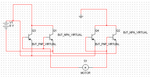
I had built a circuit that does work to a degree but the transistors TIP31(NPN) and TIP42 (PNP)·get real hot even though the motors should not be able to really harm them. Its funny because I created this circuit on a breadboard and it worked much better lol. If I apply +6v to q1-q3 collector and negative to q4-q2 collector the motor travels in one direction, switch them around and the motor travels in the other direction.
But in the spirit of doing things right, I am hoping someone can lead me to a good circuit that can be driven by my propeller to control these motors.· It has been 20 years since I left the Navy and have done much in electronics.· I have done a lot of searching but come up with so many different ways and most are to deal with stepper motors or brushless.·I thought maybe you guys would have a good idea what would work best.
Thanks,
Peter Fischel
577 x 297 - 89K
Comments
▔▔▔▔▔▔▔▔▔▔▔▔▔▔▔▔▔▔▔▔▔▔▔▔
lets see what this does... KA BOOM (note to self do not cross red and black)
perhaps you recheck your circuit. Where are the inputs? It seems to be something like a h-bridge, but it is not.
Perhaps it is easier for you to switch the direction of the motors with a relay and use only one npn-transistor per motor for the speed?
Good luck,
Christof
http://www.mcmanis.com/chuck/robotics/tutorial/h-bridge/bjt-circuit.html
The origional circuit was actually from the toy itself and made no sense to me that it would work. But tests in Electronics Workbench seemed to indicate it was sound.·Also my breadboard test worked as well.
Be that as it may,· I think the circuit that I showed in the above link would be more accurate for using with the Parallax chips.
Thank you for your responses. If anyone notices a flaw with that design, please let me know.
Thanks,
Peter
·