

MIDI OUT from inbound on/off switches
 VJ Anomolee
Posts: 15
VJ Anomolee
Posts: 15
Hello everyone,
This is my first time posting in this forum. So not entirely sure im posting this in the right category
My question is How can i use a momentary contact switches (its actually going to be 14 laser to photocell switches) to send a MIDI note on and then off value out over MIDI (which will then trigger a video on my laptop-and off value stops the video).
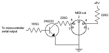
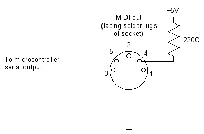
-As far as wiring i can probably use Tom Igoe's schematic from the physical computing book.
(see attached pics)
But my main hurdle is the Basic code for taking in 14 different laser to photoresistor on off switches and translating that to a MIDI note on off msgs to send out via the wired MIDI port.
Any help at all would be greatly appreciated.
This is my first time posting in this forum. So not entirely sure im posting this in the right category
My question is How can i use a momentary contact switches (its actually going to be 14 laser to photocell switches) to send a MIDI note on and then off value out over MIDI (which will then trigger a video on my laptop-and off value stops the video).
-As far as wiring i can probably use Tom Igoe's schematic from the physical computing book.
(see attached pics)
But my main hurdle is the Basic code for taking in 14 different laser to photoresistor on off switches and translating that to a MIDI note on off msgs to send out via the wired MIDI port.
Any help at all would be greatly appreciated.
350 x 172 - 8K
400 x 263 - 14K
Comments
Jeff T.
And after reading back over it i just realized that i forgot to mention that each of the fourteen will trigger a different midi note.
is that still possible using the INS command?
One link I found there that might be useful was a Nuts and Volts volume 4 PDF with a MIDI article:
http://www.parallax.com/html_pages/downloads/nvcolumns/Nuts_Volts_Downloads.asp
Andy
▔▔▔▔▔▔▔▔▔▔▔▔▔▔▔▔▔▔▔▔▔▔▔▔
Andy Lindsay
Education Department
Parallax, Inc.
For individual·notes then use a lookup table with 14 note values.
index=INS
LOOKUP index,[noparse][[/noparse]note1,note2,note3, etc. etc.], note_value
SEROUT note_value
Jeff T.
Typically, if you want a different MIDI note issued for any off to on transition, you have two word variables "oldVal" and "newVal". You initialize "oldVal" to zero and do:
oldVal = 0 do ' repeat indefinitely newVal = INS ' get the current input state newBits = !oldVal & newVal ' a bit is 1 if oldVal bit was 0 and newVal bit is 1 oldVal = newVal ' save new state for next time for i = 0 to 13 if newBits & 1 = 1 then ' check from pin 0 to pin 13 gosub sendMIDI ' send MIDI command for note "i" (0-13) endif newBits = newBits / 2 ' on to next higher I/O pin next loopHow are you coding the MIDI out? For the closures you will need another chip (or chips) to handle that many inputs.
- Stephen
-Is this true Unsoundcode, Mike Green?
Does that mean it wont work with this Basic stamp homework board - Rev. C that i have?
no time or need to upgrade the I/O
Jeff T
did i mention im new to basic and the stamp?
*cracks open the manual*
Post Edited (VJ Anomolee) : 5/5/2007 8:41:33 PM GMT
Jeff T.
Anyone have some complete MIDI out code for generating notes out?
Ive tried all the versions i found online.
as well as the nuts + volts download you guys mentioned.
all of these wouldnt compile to the chip or they simply did nothing when connecting to MIDI in (on several differnt MIDI keyboards).
such as tom igoe's code.
' {$STAMP BS2}
' {$PBASIC 2.5}
' Simple MIDI out:
HIGH 15 ' power LED on
' declare variables:
i VAR BYTE
main:
FOR i = 36 TO 96 ' a good middle range of MIDI notes
SEROUT 6, 12, [noparse][[/noparse]144, i, 64]
PAUSE 500
SEROUT 6, 12, [noparse][[/noparse]128, i, 0]
NEXT
GOTO main
Please help.
Post Edited (VJ Anomolee) : 5/6/2007 8:29:35 PM GMT
The references we've cited have working MIDI out code. The question is: "What's different about your setup that it doesn't work?".
as follows into the homework board-{ pin 5 of the midi connector is going to 220ohm res. going to pin 15(stamp), pin 4(MIDI) to 220ohm resistor to Vdd, and pin 2 (MIDI) to Vss}
MIDI connector(female) has Male to male MIDI going to MIDI in of Yamaha DX7.check this link for MIDI info on it-
http://www.maths.abdn.ac.uk/~bensondj/dx7/manuals/dx7-midi.txt
(do i need to specify some of this info to the stamp???)
Homework board has usbto232 adaptor to usb on the Macbook Pro
Running latest version of MacBS2
Communication with the stamp + compiling successful for code i put in previous post.
Audio does come out of the DX7 when pushing keys down just not via the MIDI in from the stamp
Double checked all wiring to ensure no shorts.
Here is the code on the stamp currently: (compiled with no problems)
' {$STAMP BS2}
' {$PBASIC 2.5}
' Simple MIDI out:
' declare variables:
i VAR BYTE
main:
FOR i = 36 TO 96 ' a good middle range of MIDI notes
SEROUT 15, 12, [noparse][[/noparse]144, i, 64]
PAUSE 500
SEROUT 15, 12, [noparse][[/noparse]128, i, 0]
NEXT
GOTO main
Post Edited (VJ Anomolee) : 5/6/2007 8:56:30 PM GMT
Try leaving out that 220 ohm resistor. Leave the other one (to +5V) there.
Post Edited (Mike Green) : 5/6/2007 9:09:03 PM GMT
here is a few pics of the wiring.
Post Edited (VJ Anomolee) : 5/6/2007 11:09:08 PM GMT
-really feel like there is something missing in the code
???
Maybe worth trying, I will look for the article and if I find it again will post the link.
Jeff T.
EDIT this link contains a link to code for the BS2 by Jeff Mann http://www.audiomulch.com/midipic/
Post Edited (Unsoundcode) : 5/6/2007 10:22:10 PM GMT
Jeff T
*wish i had an arduino*
Post Edited (VJ Anomolee) : 5/6/2007 11:09:58 PM GMT
▔▔▔▔▔▔▔▔▔▔▔▔▔▔▔▔▔▔▔▔▔▔▔▔
Chris Savage
Parallax Tech Support
nope no mirror effect. thats just the way it takes the pic
i will reverse them for you though- stand by for pic edits
edit- pics flipped horizontally
Post Edited (VJ Anomolee) : 5/6/2007 11:11:12 PM GMT
-and this wont compile- i get a !Symbol is already defined! error when trying to run this- "FOR" (right under doit) is highlighted
' {$STAMP BS2}
' {$PBASIC 2.5}
'constants, shouldn't change these midibaudmode CON 32780 '31.25kb, 8n1, non-inverted, open collector
'for 14-bit controllers - controller 32 is lsb of controller 0, etc. controllerLSBoffset CON 32
'MIDI status bytes:
controller CON %10110000 + midichannel
noteon CON %10010000 + midichannel
pitchbend CON %11100000 + midichannel
'declare variables
value VAR WORD 'holds the 16-bit value read from the pot
PIN VAR NIB 'which pin/pot we are reading at the moment
statusbyte VAR BYTE 'MIDI status; controller, noteon, or pitchbend
data1 VAR BYTE 'first data byte, eg. controller or note number
data2 VAR BYTE 'second MIDI data byte, eg. value or velocity
'user configuration - adjust these to suit you
'DANGER - check your circuitry and configure pins accordingly!!
'set unused pins to outputs
DIRS = %1111111111111111 'all outs
OUTS = %0000000000000000 'all low
midichannel CON 1 'MIDI transmit channel
midioutpin CON 0 'pin connected to MIDI out connector
'check the MIDI spec for a list of controller numbers you can use
controlleroffset CON 0 'add to pot's pin # to get MIDI controller #
hipot CON 15 'highest pin with a pot to measure
lowpot CON 14 'lowest pin with a pot to measure
doit:
DEBUG HOME
FOR PIN = lowpot TO hipot
'read the value of the pot
HIGH PIN
PAUSE 1
RCTIME PIN, 1, value
DEBUG "pot ", DEC PIN, " reads ", DEC value, CR
value = value >> 1 'drop the least significant bit
'send most significant 7 bits as continuous controller msg
statusbyte = controller 'sending controller message
data1 = PIN + controlleroffset 'controller #
data2 = value.highbyte
SEROUT midioutpin, midibaudmode, [noparse][[/noparse]statusbyte, data1, data2]
''uncomment this section to send 14-bit controller data
''send least significant 7 bits
'data1 = data1 + controllerLSBoffset
'data2 = value.lowbyte
'data2 = data2 >> 1 'convert to 7 bits
''use running status byte (can leave it out if unchanged)
'serout midioutpin, midibaudmode, [noparse][[/noparse]data1, data2]
NEXT
GOTO doit
Post Edited (VJ Anomolee) : 5/6/2007 11:19:48 PM GMT
Can i not just add the note on/off (SEROUT) command IF a certain resistance is measured (laser on photocell is blocked) with RCTIME on the photoresistors ?
using this code:
'What is a microcontroller- test photoresistor.bs2
'read photoresistor in RC-time circuit using RCTIME command.
' {$STAMP BS2}
' {$PBASIC 2.5}
time VAR Word
DO
High 2
PAUSE 100
RCTIME 2, 1, time
DEBUG HOME, "time = ", DEC5 time
LOOP
You could certainly do an RCTIME as you posted. Keep in mind that each RC measurement cycle (charge, then discharge and measure) will take some milliseconds and you want to do 14 of them. That may be fine for your setup or the time to go through all the measurements may be too long. You'll have to decide.
I used your code·wired·to the midi input·on the·game adapter of my soundcard·. Once I had the·software configured it played fine.
Is there something you have to configure on the keyboard maybe?
Jeff T.