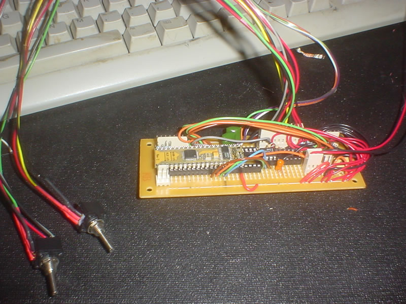
BS2p-40 AUXIO and LTC1298 problem.........Fixed
 Capt. Quirk
Posts: 872
I am having a problem interfacing my LTC1298 to the AUX side of the BS2P-40. I had everything working on my PDB as displayed in the App-Note. And·when I assembled my project I accidentally put the wires on the AUX pins.
I am using 5v power, 2 10K pots with a 220 ohm resistors going to·ch 0 &·ch1. I thought I put the 1 K resistor between DI & DO incorrectly, so I removed it and added a wire to control·DI & DO·separately. I thought perhaps I wasn't initializing the pins properly, so I added AuxIO in the "Initialization", but no where else.
Any help would be greatly appreciated
' {$STAMP BS2p}
' {$PBASIC 2.5}
'
[noparse][[/noparse] I/O Definitions ]
CS·············· PIN···· 13······ ' Orange Wire· Chip select; 0 = active
DI·············· PIN···· 14······ 'Green Wire Data IN
DO_n············ PIN···· 15······ ' Blue Wire Data OUT_.
CLK············· PIN···· 12······ ' Brown Wire· Clock to ADC; out on rising, in on falling edge.
'
[noparse][[/noparse] Variables ]
AD·············· VAR······· Word·········· ' Variable to hold 12-bit AD result.
config·········· VAR······· Nib··········· ' Configuration bits for ADC.
oddSign········· VAR······· config.BIT2··· ' Channel selection.
'
[noparse][[/noparse] Initialization ]
AUXIO
HIGH CS······· ' Deactivate ADC to begin.
HIGH DO_n····· ' Set data pin for first start bit.
HIGH DI······· ' Set data pin for first start bit.
'
[noparse][[/noparse] Program Code ]
Main:··································· ' Main loop.
· FOR oddSign = 0 TO 1·················· ' Toggle between input channels.
··· GOSUB convert······················· ' Get data from ADC.
··· DEBUG "channel ",DEC oddSign, ": ",DEC AD,CR ' Display data.
··· PAUSE 500····························· ' Wait a half second.
· NEXT···································· ' Change channels.
GOTO Main·································· ' Endless loop.
'
[noparse][[/noparse] Subroutines ]
·convert:
· config = config | %1011···················· ' Set all bits except oddSign.
· LOW CS····································· ' Activate the ADC.
· SHIFTOUT DI,CLK,LSBFIRST,[noparse][[/noparse]config\4]········ ' Send config bits.
· SHIFTIN DO_n,CLK,MSBPOST,[noparse][[/noparse]AD\12]··········· ' Get data bits.
· HIGH CS···································· ' Deactivate the ADC.
RETURN··
Post Edited (Capt. Quirk) : 5/5/2007 6:00:00 PM GMT


Comments