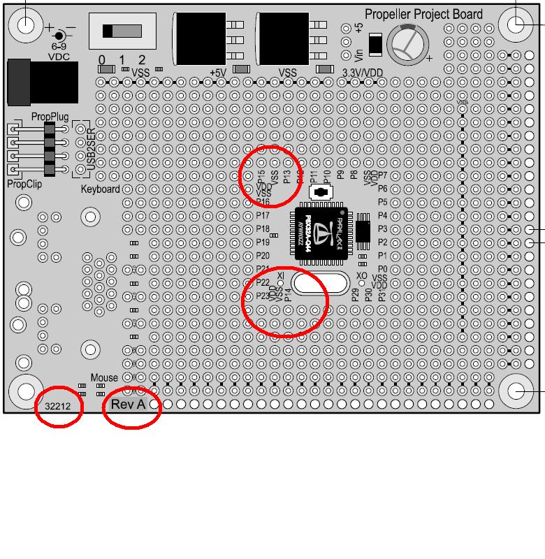
Error on Propeller ProtoBoard Layout diagram
Greetings all;
I have not found a note regarding this on any of the Forums, so this is just a heads up to note that the pinouts shown on diagram of the Prop ProtoBoard (available on the Parallax site as http://www.parallax.com/dl/docs/prod/prop/Propeller-ProtoBoard-v1.1.pdf) do not agree with the actual board printing. Both boards are shown as Rev A, with 32212 in the corner by the VGA connector, but
- the diagram shows P14 where the board has P24
- the diagram shows Vss where the board has P14
Cheers!


Comments
▔▔▔▔▔▔▔▔▔▔▔▔▔▔▔▔▔▔▔▔▔▔▔▔
Paul Baker
Propeller Applications Engineer
Parallax, Inc.