

Using SX48 to drive LARGE surplus 7-segment display panels..
 RobotWorkshop
Posts: 2,307
RobotWorkshop
Posts: 2,307
Hello,
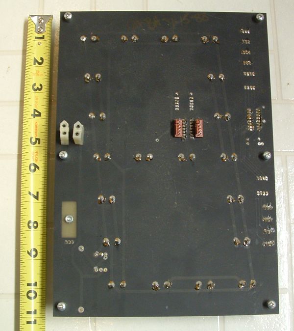
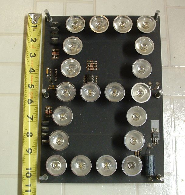
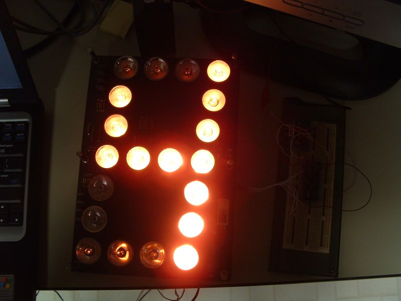
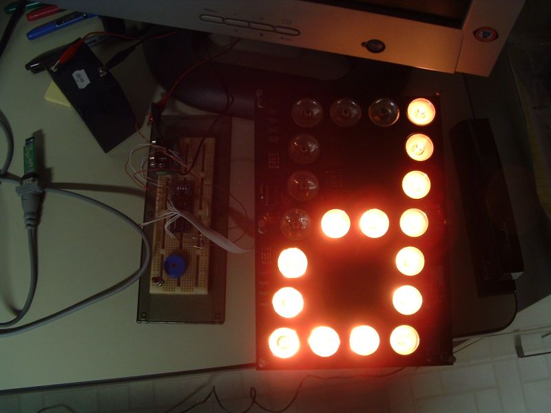
My father had picked up a bunch of surplus display panels (10.5" panels) and I finally had a chance to try and hook one of these things up. Using the SX48 and SX/B it was easy to get these going! Once I defined the pins all I had to do was:
' Where Dig is the hex digit to display (0-15)
LOOKUP Dig, 191,134,219,207,230,237,253,135,255,239,223,124,88,222,251,113, DispDig
SHIFTOUT DataP,Clock,MSBFIRST,DispDig
PULSOUT Latch,1
Multiple display panels can be cascaded to form larger displays, clock, or count down timer.
Now that it's working well i'm going to make a data sheet on it so that anyone using a similar panel can easily hook it up.
Best Regards,
Robert
600 x 674 - 65K
608 x 641 - 84K
800 x 600 - 52K
800 x 600 - 57K

891 x 724 - 138K
Comments
Looks nice.
How much current does the display draw ?
Be sure to post this in the "Completed Projects" forum when you done.
Are there any more of the display available ? I'm a display junkie [noparse];)[/noparse]
Bean.
▔▔▔▔▔▔▔▔▔▔▔▔▔▔▔▔▔▔▔▔▔▔▔▔
"Educate your children to self-control, to the habit of holding passion and prejudice and evil tendencies subject to an upright and reasoning will, and you have done much to abolish misery from their future and crimes from society"
Benjamin Franklin
- - - - - - - - - - - - - - - - - - - - - - - - - - - - - - -
www.hittconsulting.com
·
I haven't had a chance to measure the current draw yet. These use individual lamps to make up each segment. The large white power connectors on the back are for the lamp power. At the moment i'm using a 9vac 1000ma wall wart power cube as the lamp supply. The two white connectors are in parallel so you can just connect a jumper to the next display for lamp power.
Several years ago someone from the Battlebots crowd had picked up a set of these and used them with the BASIC Stamp to make a count down timer for local events. Ed M. was kind enough to let me know what the pinout was for the 6-pin connectors and saved me some time tracing them out myself.
The other two 6-pin connectors are for data in and out.
Data in:
CLK
/OE
LATCH
GND
N/C
SIN
Data out:
CLK
/OE
LATCH
GND
N/C
SOUT
These are also setup so you can just use a 6-pin jumper to the next panel. Just clock out the data (8-bits per panel) for the number of panels then latch it. For the test /OE was just tied to ground but I expect it could be used to dim the display and save power.
Once I hooked up one of these to the SX48 I added the extra characters for a through f. The connection to the SX48 is simple. Just ground, LATCH, CLK, and SIN. It was acting odd at first but that was fixed by adding 4.7K pullup resistors on the three data lines to the 5v regulator on the SX48 module.
I'm going to use a set to make a large count down timer display and i'll be glad to post it to the completed projects when it's done.
At the moment we have quite a few extra panels (more than I can ever use!) We were thinking about taking them to a Ham swap but if anyone here is interested in the extra's they would be $10 each or 6 for $50.
Best Regards,
Robert
I can paypal you the money.
Bean.
▔▔▔▔▔▔▔▔▔▔▔▔▔▔▔▔▔▔▔▔▔▔▔▔
"Educate your children to self-control, to the habit of holding passion and prejudice and evil tendencies subject to an upright and reasoning will, and you have done much to abolish misery from their future and crimes from society"
Benjamin Franklin
- - - - - - - - - - - - - - - - - - - - - - - - - - - - - - -
www.hittconsulting.com
·
Robert
I'll set another 6 off to the side for you!
Best Regards,
Robert
Best Regards,
Robert
Robert
I bought a set of these from you as well
Can you tell me if this from left to right and from which way·you need to be look at the 6-pin header
·····························1.2.3.4.5.6················· ·___________
··························· ·__________· Or is this·· ·___________
·····························__________················· 1.2.3.4.5.6
The red lines are the plastic part of the concector that is on the board
·I assume that you look at this way i am
·Which one is right
Data in:
1....CLK
2..../OE
3...LATCH
4....GND
5....N/C
6....SIN
Data out:
CLK
/OE
LATCH
GND
N/C
SOUT
▔▔▔▔▔▔▔▔▔▔▔▔▔▔▔▔▔▔▔▔▔▔▔▔
··Thanks for any·
·
·
·
·
Sam
Post Edited (sam_sam_sam) : 6/4/2007 9:04:02 PM GMT
There are 2 connectors for the data. One labeled IN and the other one OUT. Pinout is from top, with the large filter cap near the bottom of board. Pin 1 is toward the top of the board.
Data in:
1....CLK
2..../OE
3...LATCH
4....GND
5....N/C
6....SIN
To start with just tie the /OE to the GND line and make sure to add 4.7K pullup resistors on the CLK, LATCH, and SIN lines. Start with one panel to keep it simple. Then just daisy chain on the others once it is working. If you have any issues just let me know or post a follow up question here.
Best Regards,
Robert
Thank You For Your Reply
This will Help·me alot
Thank You
▔▔▔▔▔▔▔▔▔▔▔▔▔▔▔▔▔▔▔▔▔▔▔▔
··Thanks for any·
·
·
·
·
Sam