

Stumped student with DC motor problem
 Moku
Posts: 2
Moku
Posts: 2
Heyas all,
I'm taking the What's A Microcontroller class and for my project I took on the (then) simple task of making the basic stamp board the controller for a cheap remote car. It has the generic DC motors for steering and speed. My initial thought was to use the I/O pins to turn on/off the motors using the onboard battery. That doesn't work. My instructor said I should use the 2 AA batteries on the car and a transistor for switching using the I/O pin on the base. Wiring the collector to one side of the motor and the other side of the motor to + terminal of the batteries. Grounding the neg terminal and transistor emitter to Vss.
I can get that to work with 2 significant problems.
1. The motor doesn't want to start spinning on its own. A little nudge and its good to go.
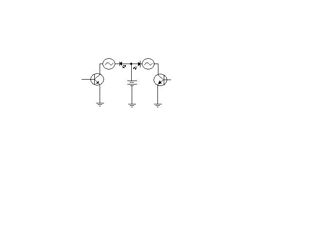
2. For left/right and Fwd/bkwd I need to switch the 2.5V to neg. I tried using an LED as a checkvalve between the batteries and motor, so I can connect the opposing transistor to the opposite motor terminals, but that only lights up the LED <with only 1 transistor wired in>. No joy with the motor.
Any help would be appreciated.
Added what I think would work as a schematic. Using 2N3904 transistors. The motors are Best Motor. Feel free to rip me a new one if it's a no brainer.
I'm taking the What's A Microcontroller class and for my project I took on the (then) simple task of making the basic stamp board the controller for a cheap remote car. It has the generic DC motors for steering and speed. My initial thought was to use the I/O pins to turn on/off the motors using the onboard battery. That doesn't work. My instructor said I should use the 2 AA batteries on the car and a transistor for switching using the I/O pin on the base. Wiring the collector to one side of the motor and the other side of the motor to + terminal of the batteries. Grounding the neg terminal and transistor emitter to Vss.
I can get that to work with 2 significant problems.
1. The motor doesn't want to start spinning on its own. A little nudge and its good to go.
2. For left/right and Fwd/bkwd I need to switch the 2.5V to neg. I tried using an LED as a checkvalve between the batteries and motor, so I can connect the opposing transistor to the opposite motor terminals, but that only lights up the LED <with only 1 transistor wired in>. No joy with the motor.
Any help would be appreciated.
Added what I think would work as a schematic. Using 2N3904 transistors. The motors are Best Motor. Feel free to rip me a new one if it's a no brainer.
bmp
900K
Comments
DC motor site:www.parallax.com
Check out the link titled "Electronic Control of DC Motors Using Discrete Bridge Circuits". It's got some excellent background information for your project.
▔▔▔▔▔▔▔▔▔▔▔▔▔▔▔▔▔▔▔▔▔▔▔▔
Andy Lindsay
Education Department
Parallax, Inc.
http://www.mcmanis.com/chuck/robotics/tutorial/h-bridge/index.html