Panning Sensor Interrupt Code Help
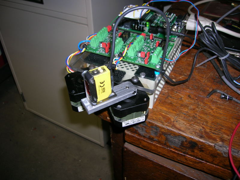
I have this diffuse reflective sensor oscillating left and right with a steper motor. My faithful assistant forced my servo beyond it stops, it doesn't work now. Servo would be much smoother·but this will work until I get another.
The sensor is 10 to 30 VDC . I've got 24V on it. Is a resistor all I need between it and the BS2 ?·Is there·an example anywhere·?
I·used a push button to simulate the input from the sensor and could not pause the scan without loosing the limit positions. Nothing I tried worked.
For now, all I want it to do is pause while sensor is made, then resume the scan.
The DISABLE HIGH stops the driver but the code keeps running, it resumes anywhere when the sensor clears.
I just disable the driver when at rest to keep the heat down. They get really hot when powered setting idle.
It senses a screwdriver handle from about 3 feet.
Code and photo attached,
Any help is greatly appreciated.
RC


Comments
2) It looks like pin 2 high enables the motor, pin 15 sets the motor direction and pin 14 steps the motor. Is that true? If not, what?
It would probably help to keep track of the theoretical motor position ... in other words, count the steps (+1 in one direction and -1 in the other direction) with some assumed initial position. You could always set up another sensor (like an LED/phototransistor pair ... set up as a photointerrupter ... with a little metal or plastic flag attached to the moving bit). During initialization, you could move the motor back and forth until the light beam got interrupted, then position the motor so the flag just moves out of the way. That would give you a reference point. Periodically, you could recalibrate the position.
The "current position" would tell you how many pulses you'd have to put out to get to some fixed position. An alternative would be to have two photointerrupters, one at either end of the turning range you want. You'd simply step the motor from one extreme to the other, but keep track of the number of pulses used from the extreme. When the sensor goes off, the count would tell you where you are.
1.
The sensor has 4 leads, 24+ and - to power it,which go to a 24v power supply.· ·1 NC out (dark sense) and 1 NO out (light sense). Both 24v. They just go high and low.
I will only use one of these outs to an input on the BS2·but it must be 5v or less.. correct ? What's the best way to step down the voltage to protect the stamp ?
2.correct on the pins but Low2 is enabled, High2 is disabled
I'd considered limit sensors at the extreme positions to reverse dir.
I will try to pulsout with no counter , a nested do..loop with a loop until... sensor IN 7.
I had that to work on a homing sequence on a machine slide before.
I guess you cannot interrupt a pulse train once it is started..
Mainly, the 24v to 5v. Best way ? Opto isolated.. ?
Thanks again,
RC
Why can't you interrupt a pulse train once it's started? Just jump out of the loop. The reason to use limit sensors is that it gives you an absolute position reference. Steppers sometimes slip. If you enable/disable them, they might slip a little bit from inertia. Over time, they'd lose position.
You still want a count, even with limit sensors. The count tells you your position between the limits when the sensor fires. I'd suggest: