Joystick on VGA >Works!
 Oldbitcollector (Jeff)
Posts: 8,091
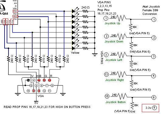
I was thinking about the addition of an Atari joystick interface for the propeller (simple stuff) except that with out some other chip to handle the I/O it requires 5 lines to handle the input. Simple digital switches. With the addition of the SD interface on those who have Demo boards, there are 4 lines left, and certainly I wouldn't want to give them up.
IIUC, the VGA output is using 240ohm resistors (in the sets) to form part of the DAC.
What if we simply grabbed lines 16,17,19,21,23 and turned them the other direction.
240ohms seem close enough, and all I'd need is a DB15M-DB9M interface to plug in.
You lose the VGA output, but gain a simple game controller for composite games.
Whats more, the demoboard might put on an interesting light show while using the joystick. (and possibly drawn the current too low?)
Those of you with engineering minds, take a look at this and tell me if this looks doable, or a good way to fry my 2nd proto board.. [noparse]:)[/noparse]
Oldbitcollector
▔▔▔▔▔▔▔▔▔▔▔▔▔▔▔▔▔▔▔▔▔▔▔▔
"Two things are infinite: the universe and human stupidity; and I'm not sure about the the universe." -Albert Einstein
Post Edited (Oldbitcollector) : 4/13/2007 1:29:52 AM GMT


Comments
I just ran some tests on pins 21 and 23 (VGA pins 1 & 2) and it seems to work with flying colors on the protoboard. (Can someone with a demoboard confirm this?
3.3v <---->PIN 23<----10K--->Grd
Of course, I discovered right away that hitting the wrong pin (ground) with 3.3v seems to reset the board. (badly I might add)
Addendum: (Thinking out loud) It looks like I can grab 5V off VGA pin 5, feed it a
little resistance, say 1K and get my adapter into a single connection.
High time to write my first object. (That is unless someone sees some potential for damage)
Oldbitcollector
Post Edited (Oldbitcollector) : 4/12/2007 5:31:57 AM GMT
Ah! (facepalm) Yes, I see what you are getting at now.. I was replicating the resistors that already existed.
Oldbitcollector
▔▔▔▔▔▔▔▔▔▔▔▔▔▔▔▔▔▔▔▔▔▔▔▔
"Two things are infinite: the universe and human stupidity; and I'm not sure about the the universe." -Albert Einstein
Post Edited (Oldbitcollector) : 4/13/2007 2:34:55 AM GMT
Built, Tested, and Documented!
I built a little in-line converter from a DB9M, DB15M and a few 10K resistors.
Disregard last two graphics, the 1K resistor needed to be upgraded to 10k
Here's a zip with both correct build information as well as a test .spin to see if it works.
Added a graphics demo using the Joystick interface, loosely based on
Chip's graphics demo routines
Oldbitcollector
▔▔▔▔▔▔▔▔▔▔▔▔▔▔▔▔▔▔▔▔▔▔▔▔
"Two things are infinite: the universe and human stupidity; and I'm not sure about the the universe." -Albert Einstein
Post Edited (Oldbitcollector) : 4/13/2007 3:21:55 AM GMT